
Views: 0 Author: Site Editor Publish Time: 2026-08-24 Origin: Site


When a servo feeder loses pitch accuracy or skews material, the entire stamping line becomes a liability. Resolving servo feeder misfeeding requires a systematic diagnostic approach. We must move away from random guesswork on the shop floor. You need to transition from simple mechanical adjustments to complex servo drive diagnostics. This logical progression determines your next operational step. You will decide between targeted repair, a system retrofit, or total equipment replacement. Misfeeding acts as a primary driver of increased scrap rates. It causes catastrophic die damage and compromises strict production schedules. Fixing it demands strict attention to roller pressure, pilot release timing, and drive feedback. You will learn how to identify hidden mechanical imbalances. You will discover proven methods to troubleshoot electrical anomalies. We will outline a standardized setup protocol to prevent recurring misalignment. This guide provides the exact steps to restore your feeding accuracy and protect your tooling.
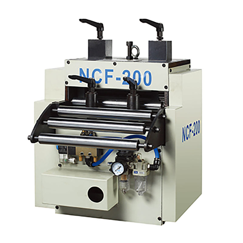
The majority of servo feeder misfeeding incidents originate from mechanical imbalances, specifically uneven feed roller pressure, overly tight material guides, or improper pilot release timing.
Electrical anomalies, such as feedback faults, thermal overheating, or power supply fluctuations, often masquerade as mechanical binding and require drive-level diagnostics.
Implementing a standardized, material-specific setup protocol is the most effective mitigation strategy against recurring misalignment and material skewing.
Evaluating whether to repair or replace a malfunctioning feeder depends on the frequency of drive alarms, parts availability, and the system's ability to handle modern, high-tensile materials.
Table of Contents
NC servo feeders must deliver precise pitch control continuously. They require consistent speed and zero material marring. You expect the material to reach the exact position for every press stroke. Acceptable tolerance thresholds vary across different stamping applications. High-speed progressive dies demand tolerances within hundredths of a millimeter. Deep drawing operations might tolerate slightly more variance. However, any deviation compromises the final part quality. The feeder must accelerate, reach top speed, and decelerate smoothly. It must position the strip exactly before the die closes. Success means the pilot pins enter the strip without dragging the material. The feed cycle must finish before the pilot release cam engages. Achieving this synchronization guarantees long tooling life and high part quality. When a machine fails to meet these baseline expectations, operators spend more time fighting the equipment than producing parts. You need a system that holds its programmed pitch regardless of coil weight or line speed.
Inaccurate feeding generates immediate and severe direct costs. You waste expensive sheet metal coil with every bad hit. Misaligned material breaks fragile punches and damages intricate die sets. These incidents force costly tooling repairs and require extensive bench work. Indirect costs multiply quickly and damage overall plant efficiency. Unplanned downtime halts the entire production line instantly. Operators waste hours troubleshooting instead of producing profitable parts. Maintenance teams pull resources from other critical plant operations. Missed delivery service level agreements damage client trust permanently. Expedited shipping costs eat into your profit margins. A single misfeed event can ruin thousands of dollars in tooling. Preventing these errors is mandatory for maintaining a profitable stamping operation. The financial drain of a poorly calibrated feeder extends far beyond the immediate scrap bin.
Direct Material Waste: Every short feed produces a rejected part, sending expensive raw material directly to the scrap hopper.
Tooling Destruction: Misaligned strips cause punches to hit half-holes, snapping carbide tooling and shattering die blocks.
Labor Drain: Maintenance technicians spend hours chasing phantom electrical faults when the root cause is often a simple mechanical bind.
Schedule Disruption: Unplanned press downtime forces production managers to reroute jobs, causing cascading delays across the entire facility.
Imbalanced material pressure springs cause major feeding errors. The sheet metal coil biases in one direction immediately. This leads directly to material skewing and inaccurate feeding. Insufficient pressure allows the feed rollers to slip against the metal. The motor turns its programmed distance accurately. However, the material falls short of the target pitch. This creates a dangerous short feed condition. Excessive pressure deforms the material surface permanently. It creates unnecessary drag across the entire feed line. The servo motor strains against this artificial resistance. The drive mechanics suffer premature wear from this constant load. You must calibrate the left and right springs perfectly. Unequal tension forces the coil to walk sideways. The material hits the die guides at an angle. This friction causes the feeder to stall or fault out. Operators often crank down the pressure bolts hoping to stop slippage, but this only exacerbates the mechanical strain.
Tightness in the die creates artificial resistance immediately. Improperly adjusted material guides disrupt the feed cycle. The feeder pushes the metal forward, but the guides pinch it. This forces the material to buckle or slip backward. Misalignment between the uncoiler, straightener, feeder, and press bends the material path. Uncorrected coil camber exacerbates this alignment issue significantly. The metal drags against the die entry constantly. This dragging causes severe servo feeder misfeeding. Operators often blame the feeder for die-related interference. You must ensure a perfectly straight material line from the coil to the die. Any deviation forces the feeder to work harder than necessary. This extra work leads to positioning errors and drive faults. A laser alignment tool can quickly reveal if your feeder is sitting off-center from the press bed.
Incorrect pilot release angles prevent proper material alignment. The pilot pins in the die must locate the material precisely. If the feeder grips the material too long, it fights the press. This synchronization failure pulls the material out of square. The resulting tension stretches the pilot holes in the strip. Operators often mistake this mechanical conflict for a drive failure. The pilot release must open exactly when the pins engage. It must close before the press lifts the material. Timing this action requires precision and a deep understanding of the press stroke. A late release binds the material against the pins. An early release allows the material to float and lose position. Both scenarios destroy feeding accuracy completely. Mechanical cam switches or programmable limit switches control this timing, and they must be verified during every die change.
Mechanical binding stops the feed cycle abruptly. Common wear parts include degraded bearings and worn gearboxes. Damaged feed rollers lose their grip on the coil. A crashed axis or jammed material forces the servo motor to work harder. Foreign objects in the mechanism create severe friction. The motor draws excessive current to overcome this resistance. This results in a complete misfeed and a drive alarm. Gearbox backlash introduces positioning errors during acceleration and deceleration. Worn universal joints in the drive train create mechanical slop. This slop prevents the motor from holding the material steady. Regular inspection of these mechanical linkages is mandatory. Replacing worn bearings prevents sudden catastrophic failures during high-speed runs. You cannot fix mechanical wear with software parameter changes.
Servo drives generate specific error codes during failures. You will often see overcurrent, overvoltage, and position tracking errors. High duty cycles cause thermal overload and overheating. Poor cabinet ventilation traps heat around the sensitive amplifier. Continuous mechanical drag forces the motor to run hot. The drive compensates for mechanical binding initially. It pushes more current to maintain the programmed speed. Eventually, it reaches its thermal limit and faults out. This causes an abrupt and dangerous feed failure. You must monitor the drive's heat sink temperature regularly. Ensure cooling fans operate at full capacity. Clean the cabinet air filters to maintain proper airflow. A cool drive ensures stable and accurate motor control. Ignoring thermal warnings will eventually destroy the internal insulated-gate bipolar transistors (IGBTs).
Compromised encoders send inaccurate position data to the controller. Resolvers can also fail under harsh stamping conditions. The drive loses track of the motor's exact position. This results in unpredictable short or long feeds. Heavy stamping vibration damages internal encoder glass disks. Oil and metal dust contaminate the sensitive feedback sensors. Reliable feedback is essential for maintaining strict pitch accuracy. You must inspect encoder cables for wear and proper shielding. A damaged cable introduces noise into the position signal. The controller misinterprets this noise as actual motor movement. This causes the feeder to jump or stutter during the feed cycle. Protecting the encoder from the stamping environment is critical. Route feedback cables away from high-voltage power lines to prevent inductive interference.
Voltage drops disrupt communication between the PLC and servo amplifier. Electrical noise or EMI corrupts the delicate command signals. You must check cable shielding and terminal connections regularly. Faulty directional control relays interrupt the feed command sequence. Loose wires cause intermittent faults that are incredibly hard to trace. A stable power supply ensures consistent motor performance. Voltage spikes can damage the drive's internal power components. Grounding the equipment properly eliminates many electrical noise issues. Separate the high-voltage power cables from the low-voltage signal cables. This prevents inductive coupling and signal corruption. A clean electrical environment is just as important as mechanical alignment. Use an oscilloscope to verify the integrity of the incoming power if you suspect supply issues.
Start with a thorough visual inspection of the entire material path. Verify material guide clearances and overall die alignment. Check the pilot release cam timing against the actual press stroke. Equalize spring pressure across the feed rollers carefully. Use feeler gauges or load cells to measure the downward force. This prevents the coil from biasing to one side. Inspect the rollers for excessive wear or material buildup. Clean the rollers with appropriate solvents to restore their grip. Verify that the straightener is not inducing a curve into the material. A flat strip feeds much more accurately than a bowed strip. Document all mechanical settings for future reference. Following a strict sequence eliminates variables one by one.
Lock out the press and feeder power to ensure safe access to the mechanical components.
Wipe down the upper and lower feed rollers with a non-residue solvent to remove stamping oil and metal fines.
Insert a feeler gauge between the rollers on the operator side and the drive side to verify parallel alignment.
Adjust the tension springs until the drag on the feeler gauge is identical on both sides of the roller assembly.
Jog the material through the feeder manually to check for any physical binding or unusual resistance.
Verify the pilot release cam engages exactly at the specified degree of the press stroke.
Symptom | Likely Root Cause | Immediate Diagnostic Action |
|---|---|---|
Material skews to the left or right | Uneven roller pressure or uncorrected coil camber | Equalize spring tension using feeler gauges; check straightener alignment. |
Consistent short feeds | Roller slippage or excessive die guide friction | Clean rollers, increase grip pressure slightly, and widen die guides. |
Drive throws overcurrent alarm | Mechanical binding, jammed material, or worn bearings | Disconnect motor and turn mechanism by hand to locate binding. |
Erratic or jumping feed lengths | Encoder feedback failure or electrical noise (EMI) | Inspect encoder cables, verify shielding, and check ground connections. |
Stretched pilot holes in material | Improper pilot release timing fighting the press | Adjust cam timing so rollers release exactly as pilot pins engage. |
Query the HMI or PLC for specific fault history immediately. Look for recurring overcurrent, tracking, and thermal alarms. Perform a motor insulation test using a megger. This checks for internal winding shorts or insulation breakdown. Inspect the cooling fans for proper operation to mitigate overheating. Verify encoder signal integrity using an oscilloscope if necessary. Clean the electrical cabinet filters to ensure adequate airflow. Measure the incoming line voltage under full load conditions. Ensure the voltage remains within the drive's specified tolerance. Check all terminal blocks for loose connections caused by press vibration. Tighten every screw terminal in the control cabinet. A systematic electrical check prevents chasing phantom mechanical issues. Record the specific fault codes to discuss with the manufacturer's technical support team.
Operators can handle simple fixes quickly on the shop floor. They can clear debris from the rollers and material path. They adjust pilot release timing and reset directional switches. Technician-level repairs require specialized skills and diagnostic tools. Maintenance personnel must replace worn bearings and rebuild gearboxes. They tune servo loops to optimize motor response and stability. Distinguish between quick adjustments and deep interventions to minimize downtime. Do not let operators adjust servo drive parameters blindly. Restrict access to critical PLC settings using passwords. Escalate complex electrical faults to trained automation engineers. Knowing when to call an expert saves hours of frustrated troubleshooting. Replacing a servo motor requires precise mechanical realignment and software homing procedures.
You must decide when a feeder is beyond economical repair. Obsolete servo motors make sourcing replacement parts impossible. Unsupported proprietary PLCs force complete system replacements eventually. Compare the immediate cost of replacing a blown servo amplifier. Weigh it against the long-term return on investment of a complete upgrade. Frequent breakdowns signal the end of the equipment's useful lifecycle. Constant repairs drain your maintenance budget and kill productivity. Evaluate the structural integrity of the feeder frame. If the mechanical foundation is solid, a controls retrofit makes sense. If the mechanics are heavily worn, a total replacement is necessary. Make this decision based on hard downtime data. Do not pour money into a machine that cannot hold mechanical tolerances.
Newer servo feeders handle advanced high-strength steels easily. They process thicker coils without stalling or slipping. Legacy equipment struggles with these demanding modern materials. Modern features provide significant production advantages and flexibility. Automated pressure adjustments eliminate operator guesswork entirely. Job recipe memory speeds up coil changeovers dramatically. Closed-loop integration with press controls ensures perfect synchronization. Modern drives offer advanced vibration suppression algorithms. This allows for faster feed rates without losing pitch accuracy. Upgrading your equipment opens the door to new business opportunities. You can quote jobs that require tighter tolerances and tougher materials. The increased throughput justifies the capital expenditure quickly. Modern HMIs also provide clear diagnostic text instead of cryptic error codes.
Relying on grey-market parts carries extremely high risk. Legacy servo drives and directional controls become obsolete quickly. You need a reliable source for replacement components. Define strict criteria for selecting a retrofit partner or OEM. Evaluate their response time and local inventory levels. Assess their technical support infrastructure before committing to a purchase. Ensure they offer comprehensive training for your operators and maintenance staff. A good vendor provides detailed electrical schematics and mechanical drawings. They should offer remote diagnostic support to troubleshoot issues quickly. Partnering with a strong vendor ensures long-term equipment reliability. Avoid proprietary systems that lock you into a single, expensive supplier. Open-architecture controls allow you to source standard components from multiple industrial distributors.
Implement a realistic daily, weekly, and monthly maintenance schedule. Daily tasks include roller cleaning and visual tension checks. Weekly tasks involve lubricating moving parts and inspecting cables. Monthly tasks require replacing cabinet filters to prevent overheating. Predictive maintenance prevents unexpected failures and costly downtime. Monitor motor current draw to detect mechanical binding early. This stops a servo feeder misfeeding event before it happens. Use thermal imaging to check for hot spots in the control cabinet. Analyze gearbox oil for metal shavings to predict bearing failure. A proactive maintenance culture is the best defense against equipment breakdowns. Document every maintenance activity to build a reliable machine history.
Inspect and clean the feed rollers daily to prevent material slippage.
Grease all zerk fittings on the drive train and roller pivot points weekly.
Check the encoder cable routing to ensure it is not rubbing against moving press components.
Vacuum the electrical cabinet monthly to remove conductive metal dust.
Verify the mechanical backlash in the gearbox quarterly using a dial indicator.
Operators often tweak settings without understanding the systemic impact. This causes severe misalignment and unpredictable feeding errors. You must mitigate these training gaps immediately through structured education. Recommend standard operating procedures for all coil changeovers. Document the exact pilot release adjustments for each specific die. Lock parameter setups to prevent unauthorized changes by untrained personnel. Proper training ensures consistent equipment performance across all shifts. Teach operators how to read and interpret basic drive alarms. Empower them to perform basic mechanical calibrations accurately. A well-trained operator is your first line of defense against scrap. Invest in their knowledge to protect your equipment. Create visual setup sheets that mount directly to the feeder control panel.
Develop a standardized coil threading procedure that every operator must follow.
Train operators to recognize the sound of a struggling servo motor before it faults out.
Require operators to log every parameter change they make during a production run.
Conduct monthly refresher courses on pilot release timing and its effect on part quality.
Audit your current feeder's fault logs to identify recurring overcurrent or tracking errors.
Standardize your roller pressure settings using load cells or feeler gauges for every coil changeover.
Verify pilot release timing against the press stroke to eliminate mechanical conflict.
Inspect encoder cables and grounding connections to rule out electrical noise interference.
Contact a specialized integration engineer for a comprehensive system evaluation if legacy parts are failing constantly.
For stamping operations where feeding accuracy, equipment reliability, and production continuity directly affect part quality and tooling life, choosing the right press and feeding equipment partner is equally important. Kinglan provides solutions for metal stamping and press line applications, supporting manufacturers in building more stable and efficient production systems based on their material, process, and automation requirements.
A: Material skewing is almost always caused by uneven feed roller pressure. If the springs on one side exert more force, the coil biases in that direction. Uncorrected coil camber or misaligned material guides can also force the material to walk sideways during the feed cycle.
A: You must calibrate the left and right pressure springs equally. Use feeler gauges between the rollers or load cells to measure the exact downward force. Adjust the tension bolts until the pressure is identical on both sides, ensuring the material is gripped evenly.
A: Yes. A tight die or pinched guides create severe artificial resistance. The servo motor draws excessive current trying to push the material through this friction. This constant strain causes the drive to overheat and eventually throw an overcurrent or thermal overload alarm.
A: These alarms indicate the motor is working harder than its rated capacity. This is usually caused by mechanical binding, jammed material, worn bearings, or excessive friction in the die. The drive shuts down to protect the motor from burning out.
A: If the feeder grips the material while the pilot pins are trying to locate it, the feeder and press fight each other. This stretches the pilot holes and pulls the material out of position, destroying pitch accuracy and mimicking a drive failure.
A: Feed rollers should be visually inspected and cleaned daily to remove oil and debris. You should check them for wear, grooving, or loss of grip monthly. Replace or regrind the rollers immediately if you detect permanent surface deformation or consistent slippage.
A: It depends on the mechanical condition. If the frame, gearboxes, and bearings are solid, retrofitting the servo drive and PLC is highly cost-effective. If the mechanics are heavily worn or you need to process thicker, modern materials, replacing the entire unit is better.



