
Views: 0 Author: Site Editor Publish Time: 2026-08-10 Origin: Site


Many buyers fixate entirely on tonnage capacity when procuring new stamping equipment. They ignore structural deformation under load. This oversight directly causes unexplained part rejection rates and skyrockets tooling maintenance costs. During the stamping cycle, micro-deflections occur across the press structure. These microscopic movements force punch-to-die misalignment right at the point of impact. The immediate results include poor dimensional accuracy, excessive burr formation, and heavily compromised surface quality.
Evaluating power press frame rigidity serves as the absolute foundation for specifying any stamping machinery. Tonnage simply dictates the raw force available. Frame rigidity dictates exactly how accurately you apply that force to the sheet metal. We will break down the mechanics of structural deflection, assess different frame architectures, and align press designs with specific production tolerances to eliminate die wear.
Table of Contents
Rigidity Over Tonnage: Tonnage dictates the force available, but frame rigidity dictates how accurately that force is applied. Excessive deflection compromises even the most precisely machined dies.
Frame Geometry Dictates Deflection Profiles: C-frame (gap-frame) presses inherently suffer from angular deflection due to throat depth, whereas straight-side (H-frame) presses offer symmetrical load distribution for high-precision applications.
Direct Impact on Tooling ROI: Poor frame rigidity accelerates die wear, increases maintenance intervals, and amplifies the destructive effects of snap-through (reverse tonnage).
Application-Specific Specification: High-tensile materials, thick plate stamping, high-speed operations, and complex progressive dies require significantly higher rigidity baselines than standard blanking operations.
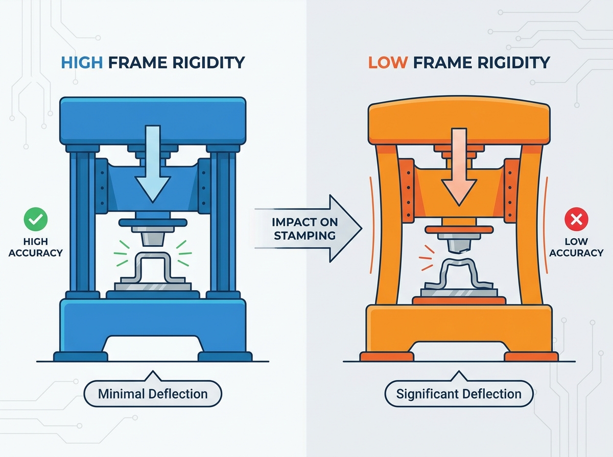
Press strength and press rigidity represent two entirely different mechanical properties on the shop floor. Press strength prevents catastrophic failure. It ensures the machine does not crack, fracture, or break under maximum tonnage. Press rigidity resists elastic deformation. It dictates exactly how much the cast iron or welded steel frame stretches or bends during the actual stamping cycle. Stamping forces cause all metal frames to flex. You cannot stop physics. The engineering goal is to control and minimize this flex to acceptable micrometer levels.
Stress on the frame must remain intentionally low to achieve maximum possible rigidity. Engineers design press frames with massive, over-engineered cross-sections. This extra material does not just prevent breakage. It keeps the elastic deformation tightly constrained. High rigidity prevents damage to the press frame itself. It also protects the applied force mechanisms, including the crankshaft, pitman arms, and connection points, from absorbing destructive kinetic energy. When a frame flexes excessively, the internal drive components bind, squeezing out the protective oil film in the bearings and causing rapid bronze wear.
Deflection occurs in two primary modes during a press stroke. Parallel deflection is the vertical stretch of the frame. The slide and the bed remain perfectly parallel during this stretch. The entire frame elongates uniformly under the stamping load. This vertical stretch affects the bottom-dead-center (BDC) position. However, it does not tilt the tooling out of square. Operators can often compensate for parallel deflection by adjusting the shut height.
Angular deflection is yaw or tilt. The slide and the bed lose parallelism. This occurs when the frame bends unevenly from front to back or side to side. Angular deflection stands as the primary enemy of dimensional accuracy. It destroys die alignment instantly. A tilted ram forces the punch into the die matrix at a severe angle. This eliminates the uniform cutting clearance required for clean metal fracture, causing the punch to shave the die wall and generate severe lateral forces.
A highly rigid bed and bolster arrangement prevents localized deflection directly beneath the tooling. The bed must support the bolster plate without bowing under concentrated loads. A bowing bed distorts the die shoe. This distortion translates directly into the stamped part, causing warped blanks, inconsistent coining depths, and springback variations across the sheet metal.
A massive, well-ribbed bed maintains a flat reference plane. This plane remains stable during the entire stamping, blanking, and punching cycle. Proper bolster thickness distributes the concentrated stamping loads over a wider surface area. It transfers these loads evenly into the press frame uprights. This prevents the center of the die from sinking during heavy forming operations. When evaluating a press, check the bed deflection specifications; a standard benchmark is 0.0015 inches of deflection per foot of bed length under full load.
Dimensional consistency relies entirely on tolerance control at the bottom of the stroke. Frame stretch directly impacts bottom-dead-center repeatability. The ram must reach the exact same position every single stroke to maintain part quality. Elastic stretch changes this terminal position dynamically based on the material resistance. If the frame stretches by 0.1 millimeters under load, the punch stops 0.1 millimeters short of its target depth.
Rigidity ensures consistent BDC positioning. This consistency is critical for coining and forming tolerances. Coining requires the punch to squeeze the material into a specific, tightly controlled shape. Any variation in ram travel alters the final part thickness. A rigid frame guarantees the applied force translates into material deformation, not machine deformation. Facilities stamping high-precision electronics or aerospace components often use linear variable differential transformers (LVDTs) to monitor this BDC repeatability in real-time.
Frame tilt alters cutting clearances dynamically during the stroke. Punch-to-die misalignment occurs the millisecond the punch contacts the material. A standard cutting clearance might be ten percent of the material thickness. Angular deflection shifts the punch laterally. The clearance drops to two percent on one side and increases to eighteen percent on the opposite side.
This misalignment leads to uneven burr distribution. Tearing happens on the material edge with excessive clearance. The tight side experiences secondary shearing and galling. Edge quality degrades rapidly, forcing operators to add secondary deburring operations. A rigid frame maintains uniform clearance around the entire punch perimeter.
To troubleshoot edge quality issues related to rigidity, follow these steps:
Inspect the stamped blank for uneven burr heights across opposite edges using a micrometer.
Measure the die clearance using feeler gauges with the ram at rest, then compare it to the wear patterns on the punch.
Check the gib clearances on the press slide to ensure the ram is not shifting laterally before impact.
Mount dial indicators between the bed and the slide to measure angular deflection during a slow-motion test stroke under load.
Review the tonnage monitor to ensure the station is not exceeding the localized capacity of the press bed.
Material fractures violently during the cutting cycle. The press builds massive tonnage to push the punch through the high-strength metal. When the material finally shears, resistance drops to zero instantly. The stretched press frame violently snaps back to its resting state. This creates severe snap-through shock, commonly known as reverse tonnage.
A highly rigid frame absorbs this stamping vibration effectively. Massive cast iron components, like Meehanite, contain graphite flakes that naturally dampen kinetic energy. Heavily ribbed steel weldments also dissipate this force. This mitigates secondary damage to the part surface. It prevents the punch from bouncing back into the material and leaving witness marks. Superior rigidity also protects press components from destructive shockwaves that loosen fasteners, crack welds, and shatter carbide die sections.
High-speed stamping operations run at hundreds of strokes per minute. This rapid speed amplifies the effects of poor rigidity exponentially. The frame does not have time to settle between strokes. Rapid dynamic loading creates harmonic vibrations. These vibrations compound rapidly if the frame lacks sufficient stiffness.
Exceptional structural stiffness prevents harmonic vibrations from taking hold. It stops the machine from shaking itself out of alignment. High-speed presses require specialized frame designs to handle these dynamic forces. Without high rigidity, vibration destroys part consistency and causes rapid fatigue in the tooling components. Operators will notice parts drifting out of tolerance as the press heats up and the vibrations alter the running clearances.
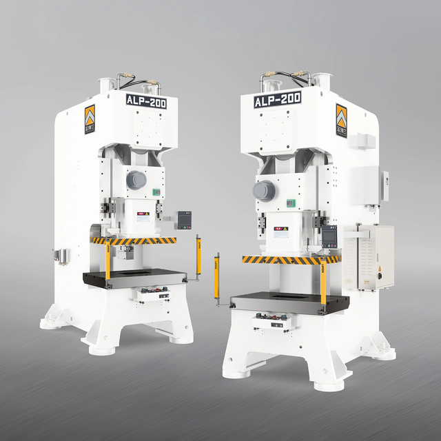
The C-frame design offers distinct accessibility benefits on the shop floor. Operators enjoy three-sided access to the tooling area. This makes die changes fast and efficient. It allows for easy integration of automated feeding equipment from multiple angles. However, the structural drawbacks are significant. The open front creates a massive cantilever effect.
Throat depth directly correlates to this cantilever effect. A larger throat depth exponentially increases angular frame deformation. The top half of the "C" bends upward and backward under heavy load. The ram tilts away from the operator. This angular deflection increases stamping vibration and causes the punch to enter the die at an angle. It makes C-frames unsuitable for high-precision, tight-tolerance progressive die work. They are best reserved for light blanking or secondary operations where tolerances are generous.
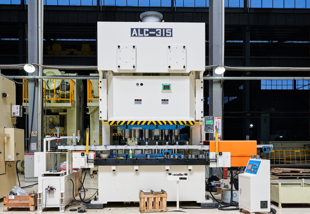
The straight-side architecture offers a robust solution for demanding applications. The H-frame design features a four-pillar, symmetrical structure. This closed-loop design eliminates the open front of the C-frame entirely. The symmetrical support prevents the frame from bending backward. It effectively eliminates angular deflection under centered loads.
This design provides superior strength for high-speed operations. High-tonnage operations also require this architecture to maintain part quality. The vertical stretch remains perfectly parallel. The punch enters the die perfectly straight every time. H-frame presses represent the industry standard for progressive die stamping, heavy forming, and high-precision manufacturing where die protection is paramount.
Press frames utilize either solid or tie-rod construction methods. Solid cast or welded frames offer baseline stiffness for smaller tonnages. The entire frame acts as a single structural unit. Pre-stressed tie-rod constructions offer advanced rigidity for larger presses. The frame consists of a separate crown, bed, and two uprights.
Massive steel tie-rods hold these four components together. Hydraulic nuts pre-tension these tie-rods to 150-200% of the press capacity. This pre-stressing compresses the uprights heavily. The frame will not stretch until the stamping force exceeds the pre-tension force. This neutralizes frame stretch during the standard stamping cycle, keeping the BDC position rock solid even under maximum tonnage.
Structural Feature | C-Frame (Gap Frame) | Straight-Side (H-Frame) |
|---|---|---|
Deflection Profile | High angular deflection (yaw/tilt) under heavy loads. | Parallel deflection only; zero angular tilt when center-loaded. |
Tooling Accessibility | Excellent three-sided access for manual or automated feeding. | Limited to front and rear windows; requires precise feed alignment. |
Ideal Application | Light blanking, single-station tooling, secondary operations. | Progressive dies, heavy forming, AHSS, high-speed stamping. |
Overall Rigidity Level | Low to Moderate depending on throat depth. | Extremely High due to four-pillar symmetrical support. |
Off-Center Load Handling | Poor; twists easily under asymmetrical forces. | Excellent; wide slide and 8-point gibs resist tipping. |
Modern servo press technology interacts directly with frame design. Servo motors allow for fully programmable stroke profiles. Operators can slow the ram velocity exactly at bottom-dead-center. This drastically reduces the snap-through shock when the material fractures. It lowers the dynamic stress placed on the machine and the tooling.
However, servo technology does not replace the need for structural stiffness. The press still relies on a fundamentally rigid frame to guide the tooling. Programmable strokes cannot fix angular deflection caused by a weak frame bending under tonnage. A servo drive paired with superior power press frame rigidity delivers the ultimate dimensional accuracy and extends die life significantly. The frame provides the physical foundation, while the servo provides the kinetic control.
Poor rigidity carries severe hidden costs on the production floor. Lateral movement of the punch shaves the die matrix. When angular deflection tilts the ram, the punch strikes the side of the die cavity instead of passing cleanly through the center. This metal-on-metal contact causes micro-chipping on the carbide cutting edges. The tooling degrades rapidly.
This requires more frequent sharpening in the tool room. Pulling a die, tearing it down, grinding the sections, shimming them back to height, and re-timing the tool consumes massive amounts of labor. Total die life drops significantly. A die designed for one million strokes might fail at two hundred thousand. Maximizing frame stiffness keeps the punch perfectly centered, preserving the expensive tooling and reducing unplanned downtime.
Excessive frame deflection hurts the machine itself. The twisting and bending place uneven wear on internal mechanical components. Gibs experience severe lateral pressure as the frame distorts. Slide guides wear out prematurely on one side. Bearings endure asymmetrical loading during the stroke, squeezing out lubrication and causing metal-to-metal contact.
This leads to premature mechanical failure. Clearances open up, further reducing stamping accuracy. Unplanned downtime increases as maintenance teams replace worn bronze liners, pitman connections, and main bearings. A rigid frame keeps all moving parts in perfect alignment. This extends the lifespan of the entire mechanical system and keeps the press running production instead of sitting in maintenance.
Material thickness dictates the required cutting forces. Advanced High-Strength Steels (AHSS) require massive tonnage to shear. Tensile strengths exceeding 1000 MPa are common in modern automotive stamping. These materials do not yield easily. They build immense pressure before suddenly fracturing.
This creates severe snap-through energy. Stamping AHSS requires disproportionately higher frame rigidity. A standard press will suffer severe reverse tonnage damage. Specifying equipment for AHSS demands oversized frames, heavy-duty tie-rods, and specialized shock dampeners. Baseline rigidity must exceed standard blanking requirements to handle the violent energy release without destroying the press crown.
Tooling type heavily influences frame selection. Single-station tooling usually centers the load directly under the ram. Progressive dies feature severe off-center loading. The material moves through multiple stations simultaneously. Piercing, coining, and blanking happen at different ends of the die at the exact same time.
Forces distribute unevenly across the slide. These applications demand the symmetrical rigidity of an H-frame. A C-frame will twist violently under this off-center load. The H-frame prevents ram tipping. It supports the slide evenly across all four corners, ensuring every station hits its target depth simultaneously without binding the guide pins.
Evaluate a press based on its ability to handle off-center loads. Slide length plays a major role in this capability. A longer slide distributes off-center forces over a wider area of the gibs. Gibbing design is equally critical. Eight-point bronze gibs constrain the slide in all lateral directions.
They prevent the ram from shifting front-to-back or left-to-right. Overall frame stiffness dictates the success of the gibbing system. If the frame bends, the gibs move with it, rendering them useless. High rigidity combined with eight-point gibbing provides the ultimate defense against off-center tooling loads, keeping the slide parallel to the bed at all times.
Press specifications do not operate in a vacuum. Frame stiffness works in tandem with other mechanical features to produce good parts. Gib clearance must remain tight. The drive type determines the velocity of the impact. The tonnage rating must exceed the application requirements by a healthy margin.
This synergy determines the final output quality. Dimensional accuracy relies on all these factors working together seamlessly. Surface quality and consistency depend on a rigid foundation. Evaluating a press requires looking at the complete mechanical system, starting with the structural frame.
Follow these steps when specifying a new press:
Calculate the maximum required tonnage, including a 20% safety factor for material thickness variations.
Determine the maximum off-center load generated by your most complex progressive die using tonnage monitors.
Select a frame architecture (C-frame or H-frame) that matches the off-center loading requirements.
Specify tie-rod construction if the application involves high-tensile materials or severe snap-through shock.
Verify the bed and bolster thickness can support the die shoe without bowing under maximum tonnage.
Review the gibbing design to ensure it provides adequate lateral support for the slide length.

Over-tonnaging is a major operational risk in any stamping facility. Using a press at 100% of its rated capacity for continuous production causes excessive deflection. The frame stretches to its maximum elastic limit on every single stroke. This destroys tooling and accelerates machine fatigue rapidly.
Size the press appropriately for the job. The required stamping tonnage should fall between 60-80% of the machine's rated capacity. This buffer minimizes deflection. It keeps the frame well within its most rigid operating window. Upsizing the press tonnage is the simplest and most effective way to increase effective rigidity on the shop floor.
A rigid frame needs a stable foundation to function correctly. Inadequate installation ruins structural integrity instantly. Placing a heavy press on a standard 6-inch factory floor causes the concrete to crack. The machine will settle unevenly over time. This introduces twist into the frame before it even cycles a single part.
Use proper vibration isolation pads to dissipate kinetic energy into the floor safely. Level the machine precisely using precision machinist levels on the bed. Large presses require reinforced concrete foundations. Deep pits with specialized epoxy grout and concrete mixtures isolate the stamping shockwaves from the rest of the facility. A rigid machine requires a rigid floor to maintain its accuracy.
Audit your current scrap rates and investigate edge quality issues to identify potential frame deflection problems.
Review your die maintenance logs for signs of uneven wear, micro-chipping, or frequent sharpening requirements.
Calculate your true tonnage and off-center loading requirements for all active progressive dies.
Consult a press manufacturer to run deflection simulations for your specific tooling before purchasing new equipment.
Founded in 1983, Zhejiang Jinaolan Machine Tool develops mechanical presses and integrated stamping-line equipment, including feeding systems, dies, and transfer solutions. With press capacities ranging from 25 to 2,400 tons, the company supports manufacturers in matching frame design, automation, and production requirements to demanding stamping applications.
A: Throat depth creates a cantilever effect in C-frame presses. A larger throat depth increases the unsupported section of the frame. This leads to exponentially greater angular deformation under load. The ram tilts away from the bed, increasing stamping vibration and destroying tooling alignment.
A: Press strength prevents the frame from permanently breaking or cracking under maximum tonnage. Press rigidity prevents the frame from flexing or stretching elastically during the stroke. A press can be strong enough to avoid breaking but lack the rigidity needed for accurate stamping.
A: The H-shape provides symmetrical support on all four corners of the slide. This closed-loop structure eliminates the angular deflection inherent in open-front C-frames. The ram travels perfectly parallel to the bed, ensuring uniform cutting clearances and precise bottom-dead-center repeatability.
A: Poor rigidity allows the ram to shift laterally during the stamping cycle. This forces the punch to strike the side of the die matrix. The metal-on-metal contact causes micro-chipping, requiring frequent sharpening and drastically reducing the total lifespan of the tooling.
A: Snap-through shock occurs when the stamped material suddenly fractures. The resistance drops to zero instantly. The press frame, which was stretched under heavy tonnage, violently snaps back to its resting state. This creates severe reverse tonnage and destructive vibration.
A: AHSS possess extremely high tensile strength. They require massive cutting forces and build immense pressure before fracturing. This generates severe snap-through energy. A highly rigid press frame is required to absorb this violent shock without suffering mechanical damage or losing accuracy.



