
Views: 0 Author: Site Editor Publish Time: 2026-09-21 Origin: Site


Selecting a power press dictates your facility footprint, production speed, and die life. Plant managers and manufacturing engineers face a constant balancing act on the shop floor. You must weigh the need for rapid tooling changes against the structural rigidity required for high-precision stamping. Agile manufacturing demands operator accessibility, while heavy tonnage requires absolute stability. The open-gap press provides a highly versatile solution for specific operational envelopes. You must conduct a rigorous evaluation of its structural advantages and physical limitations before installation. A standard C frame power press offers distinct operational benefits for job shops and high-mix production environments. We will explore how this architecture influences daily production and define the exact engineering thresholds where this design excels.
Superior Accessibility: The open-front, three-sided access of a C frame power press significantly reduces tooling changeover times and simplifies robotic or manual part loading.
Unmatched Versatility: The open-gap design allows for the processing of oversized or odd-shaped materials that extend beyond the press bed, a physical impossibility in enclosed frame designs.
Structural Trade-offs: The inherent open-gap design introduces angular deflection (yaw) under maximum load, making it unsuitable for applications requiring extreme dimensional stability at high tonnages.
Optimal Use Cases: Highly effective for small to medium-volume blanking, piercing, and light forming operations where speed, versatility, and footprint efficiency outweigh the need for absolute rigidity.
Scalability Limits: Facilities scaling into heavy deep drawing or utilizing complex, high-station progressive dies will eventually need to transition from C-frame to straight-side (H-frame) architectures.
Table of Contents
A C frame power press uses an open-front structure to provide easy access for tooling and material handling. Unlike closed-frame presses, it has no front support columns, creating a more flexible working area. The rear frame absorbs the main operating force, while the throat depth determines how far materials can extend into the press.
Because the frame is open, heavy loads can create slight deformation during operation. The front section may move under high pressure, which can affect slide alignment and part accuracy. Therefore, selecting the right application is important to ensure reliable performance.
Before choosing a C frame press, engineers should evaluate:
Required tonnage based on material thickness and forming requirements.
Bed size to ensure the die is fully supported.
Stroke length for part removal and automation needs.
Production speed requirements (SPM).
Acceptable deflection levels based on part accuracy requirements.
The open three-sided structure makes die changes faster and easier. Operators can access the press from multiple directions, allowing forklifts and die carts to move directly to the work area.
This design reduces setup time and improves operator efficiency. It also provides better visibility during production, making inspections, adjustments, and maintenance easier.
Key benefits:
Faster die replacement
Better operator access
Easier material loading and unloading
Improved workplace ergonomics
C frame presses provide excellent flexibility for oversized or unusual workpieces. The open sides allow long sheets, profiles, and large components to pass through the press area easily.
This makes them suitable for manufacturers producing different part sizes on the same machine.
Common applications include:
Metal brackets
Long steel channels
Appliance components
Custom fabricated parts
The open structure simplifies automation installation. Feeders, robots, conveyors, and scrap systems can be integrated without major structural limitations.
Material can move smoothly through the stamping process, improving production efficiency. Smaller C frame presses can also achieve high stroke speeds, making them suitable for fast punching and blanking operations.
Automation advantages:
Simple feeder installation
Flexible material flow
Easy robot access
Higher production efficiency
C frame presses require less floor space compared with closed-frame presses of similar capacity. Their compact structure allows easier factory layout and better use of production space.
The smaller footprint also reduces installation costs and allows multiple machines to be arranged in compact production cells.
Main advantages:
Lower space requirements
Easier factory integration
Reduced equipment investment
Flexible production layout
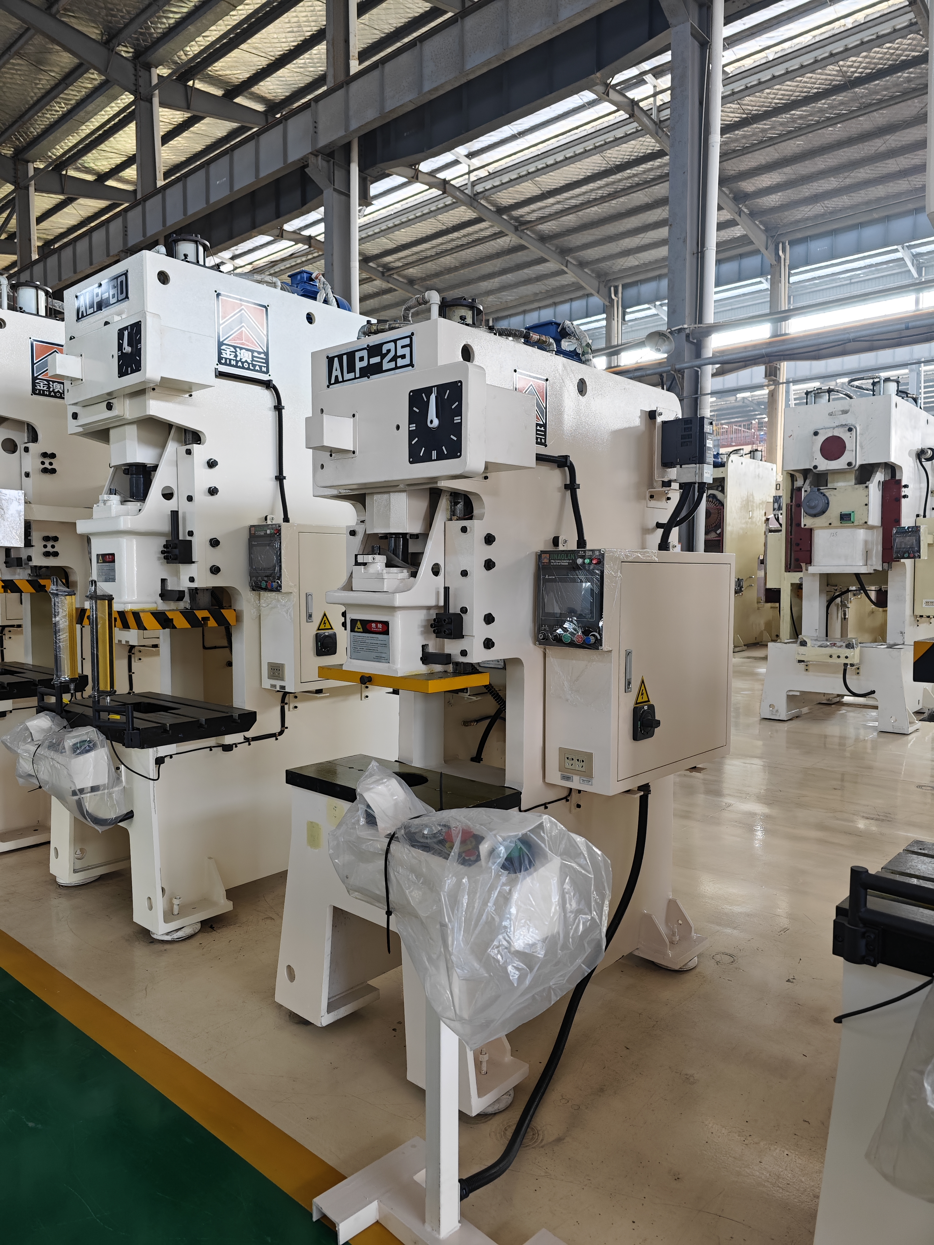
We must examine the physics of frame gaping. Tooling engineers refer to this as "yaw." The C-shape naturally tends to open slightly under peak tonnage. The front of the slide deflects upward, and the front of the bed deflects downward. This creates a microscopic but measurable loss of parallelism. Physics dictates that cantilevered structures flex under extreme loads. You can expect a certain amount of deflection per inch of throat depth, usually measured in thousandths of an inch.
This angular deflection directly impacts part tolerance. You cannot run high-precision coining operations on an open-gap frame. The required tonnage at BDC will spring the frame, causing uneven coin depth across the part. Heavy embossing operations suffer from the same uneven depth. Operations requiring perfect slide-to-bed parallelism will fail. You cannot force an open-gap press to hold aerospace tolerances under maximum load. The structural geometry simply prevents absolute rigidity.
Frame deflection correlates directly with uneven punch-to-die clearance. As the frame yaw increases, the punch enters the die matrix at a slight angle. This destroys the concentricity of the cutting clearance. If you are running cold rolled steel with a tight clearance, a frame deflection of just 0.004" means the punch crashes into the die block. One side of the punch rubs heavily against the steel. The opposite side experiences excessive clearance, pulling a massive burr on the stamping.
Accelerated tool wear presents a severe operational risk. Chipping occurs when punches misalign during entry. Catastrophic die failure remains a real possibility if the guide pins bind. Pushing an open-gap press to its maximum tonnage capacity invites these failures. You spend more time in the tool room sharpening dies and replacing broken punches. Ignoring deflection physics guarantees premature tooling destruction.
C frame presses usually have a practical tonnage limit of around 200–300 tons. Beyond this range, the required reinforcement increases significantly, making straight-side presses more suitable for maintaining stability and load balance. These presses are not ideal for heavy deep drawing, large progressive dies, or high-force blanking of high-strength materials, as uneven loading and impact forces can cause frame deformation and tooling damage. Selecting the correct press structure based on the application is essential for reliable performance.

Choosing the right press requires analyzing your specific production variables. High-mix environments demand rapid changeovers. Low-mix environments prioritize long-term stability. You must map your part complexity against machine capabilities. The following matrix contrasts the operational realities of both architectures to guide your procurement strategy.
Operational Metric | C-Frame Press | H-Frame (Straight-Side) Press |
|---|---|---|
Production Mix | High mix, frequent changeovers | Low mix, dedicated production runs |
Tooling Complexity | Single-hit or short progressive dies | Long, complex progressive dies |
Loading Access | Three-sided, highly accessible | Restricted by front/rear pillars |
Deflection Profile | Angular deflection (yaw) under load | Symmetrical vertical deflection |
Footprint | Compact, space-efficient | Large, requires significant floor space |
Operator fatigue varies significantly between these designs. The enclosed design of H-frames presents loading challenges. Operators must reach through narrow windows to clear scrap or adjust material. Setting up heavy dies requires specialized equipment and careful maneuvering. Contrast this against the open accessibility of C-frames. The open front reduces physical strain during manual operations and speeds up every interaction with the tooling.
We must contrast the physical durability of the machine architectures. The open-gap machine offers high durability for appropriate tasks. However, misapplication leads to severe long-term tooling maintenance requirements. If you constantly push the machine to its deflection limits, your dies will suffer. The frame itself may survive the stress, but your tooling will degrade rapidly, requiring constant sharpening and replacement.
H-frame presses offer vastly superior die protection. Their symmetrical design ensures excellent precision retention over millions of cycles. The slide remains perfectly parallel to the bed, even under heavy snap-through shock. This protects delicate punches and extends sharpening intervals significantly. However, this precision requires a larger footprint and longer changeover times. You trade agility for absolute dimensional stability.
Engineers strongly recommend the "20% rule" for press sizing. You should specify a machine with a tonnage capacity 20-30% higher than your calculated requirement. This buffering minimizes the effects of angular deflection. Running an 80-ton job on a 100-ton press keeps the frame in its rigid zone. This standard engineering practice protects both the machine and the tooling.
Never size an open-gap press exactly to your peak tonnage requirement. Mechanical presses only deliver their rated tonnage at a specific distance above BDC, usually 1/8" or 1/4". If you hit the material higher up in the stroke, you have significantly less tonnage available. Operating constantly at 100% capacity maximizes frame yaw. This practice guarantees premature wear on gibs and bearings. Tonnage buffering acts as an operational safety net. It ensures consistent part quality across long production runs.
Tooling engineers must adapt their designs for this specific architecture. You cannot rely on the press slide to guide the tooling. You must utilize heavy-duty guided die sets. Incorporate robust four-post die shoes with oversized guide pins and ball bearing bushings. These components absorb the inherent yaw of the press. They force the punch and die to remain aligned despite frame deflection.
Center the heaviest cutting loads directly under the slide centerline. Avoid placing high-tonnage stations near the front edge of the die, as this exacerbates the bending moment. If you are running operations with heavy side-thrust, like cam piercing or deep forming, you must install heel blocks. Heel blocks engage before the punch hits the material, absorbing the lateral forces and protecting the guide pins from snapping. Proper tooling design neutralizes the structural disadvantages of the open frame.
Some manufacturers offer structural enhancements for open-gap models. Temporary tie-rods can connect the front of the slide to the bed. These front supports temporarily increase overall rigidity. You bolt them in place for specific, higher-tolerance production runs. They effectively convert the machine into a closed-frame hybrid, preventing the clamshell effect.
These retrofits reduce accessibility while installed. You lose the ability to slide dies in from the front. However, they drastically reduce angular deflection. You remove them when returning to standard blanking operations. This modular approach expands the operational envelope of the machine. It provides a flexible solution for facilities with highly variable part tolerances.
Strict preventative maintenance routines ensure long-term machine durability. Maintenance teams must focus heavily on gib clearance adjustments. Pull feeler gauges across the gibs quarterly. You want to maintain the manufacturer's specified running clearance, typically around 0.0015" to 0.002". Loose gibs allow the slide to kick laterally during snap-through, exacerbating the natural yaw of the frame. Tight gibs maintain slide parallelism during the downward stroke.
Regular slide parallelism checks remain mandatory. Mount a magnetic base dial indicator to the bolster plate and sweep the bottom of the slide at BDC. If the slide is out of parallel front-to-back by more than 0.002" per foot, you need to shim the tooling or scrape the gibs. Monitor frame stress points for micro-cracking. Inspect the rear frame radius where stress concentrates. Proactive maintenance prevents catastrophic mechanical failures and maintains production accuracy.
Before issuing a purchase order for your next stamping press, execute the following engineering steps to ensure the equipment matches your production reality:
Calculate the exact off-center loading requirements and reverse tonnage shock for all active dies scheduled for the new machine.
Consult with your tooling department to determine the maximum acceptable angular deflection based on your tightest part print tolerances.
Request finite element analysis (FEA) data from the press manufacturer to verify how the specific frame casting behaves under your calculated peak loads.
Audit your current die inventory to ensure all tools utilize heavy-duty guide pins and heel blocks capable of neutralizing inherent frame yaw.
A: The standard range typically falls between 10 to 250 tons. Manufacturers rarely build them larger because the massive frame thickness required to prevent deflection becomes impractical. For requirements exceeding 300 tons, the industry shifts to H-frame designs to maintain necessary structural integrity and symmetrical force distribution.
A: Short progressive dies function well in these machines. However, long progressive dies suffer from severe off-center loading. As the material moves through multiple stations, the uneven force distribution exacerbates frame deflection. This causes rapid tool wear and tolerance issues at the outer edges of the die.
A: No, deflection cannot be completely eliminated due to the physics of the cantilevered design. However, you can effectively mitigate its impact. Proper press sizing, rigorous gib maintenance, and the mandatory use of heavy-duty guided die sets ensure that the tooling remains aligned despite the frame's natural yaw.
A: Yes, they offer exceptionally high compatibility with automation. The open-front and clear side access make robotic loading and unloading highly efficient. Robotic arms can maneuver freely without navigating around the restrictive front pillars found on enclosed frame designs, simplifying cell integration.
A: Yes, this represents one of its primary advantages. The open-gap design allows oversized or odd-shaped materials to extend out the sides of the press. This lateral openness provides superior versatility for custom fabrication, allowing you to process long extrusions or wide panels easily.
A: A mechanical press utilizes a flywheel and clutch to deliver a rapid, high-impact stroke, ideal for high-speed blanking. A hydraulic press uses fluid cylinders to deliver adjustable force and controlled dwell times throughout the entire stroke, making it better suited for deep drawing and precise forming within the open-gap architecture.



