
Views: 0 Author: Site Editor Publish Time: 2026-11-09 Origin: Site


Use transfer die stamping when the workpiece needs to move independently between stamping operations and the production program can justify dedicated handling and tooling. It is especially worth evaluating when a carrier strip would interfere with material flow during drawing, limit access for trimming or flanging, or force an inefficient strip layout. Before committing, confirm that the blank and each intermediate shape can be gripped, moved, and located reliably at the required production rate.
Table of Contents
A deep housing, shell, or pan may require an initial draw, a redraw, and later trimming or flanging. If keeping the workpiece attached to a carrier restricts material flow or makes a later operation difficult to reach, moving it as a separate piece gives the die designer more freedom to lay out the process.
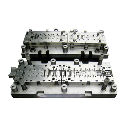
The draw depth alone does not determine the choice. Review the blank shape, draw direction, radii, material grade, and thinning limits. Ask where the sheet needs to flow and whether carrier attachment points would interfere with that movement. For parts that require several draws, check how the first formed shape will be supported and located before the next hit.
A draw station may need to support the part around its perimeter. A later trim or flange station may need access to the same edge. Transfer tooling lets the team plan how to handle and locate the part at each stage. A change in orientation can also be evaluated if the transfer equipment and tooling can accommodate it.
Lay out the gripping points before the tooling concept is finalized. A flange that is easy to grip after drawing may disappear during trimming. A visible surface may need to stay clear of gripper marks. Review the flat blank and every intermediate shape, including how the finished part leaves the final station.
A progressive strip may require carrier webs or additional strip width to keep the part stable through several stations. A transfer process can use blanks cut separately or blanks separated at the beginning of the line. That gives the team another way to lay out the blanks and compare material consumption.
Compare the actual layouts. Include blanking skeleton, edge trim, carrier scrap, and startup losses. If the transfer concept uses pre-cut blanks, include the cost of making, stacking, and feeding them. A smaller blank can improve material utilization while adding handling cost elsewhere in the process.
In transfer die stamping, a mechanism moves a separated blank or partially formed part from station to station. In progressive die stamping, the workpiece typically stays attached to a carrier strip through successive stations until it is cut free. With single-stage tooling, each die performs a stage, and a part that needs more operations must be moved to additional tooling.
Selection factor | Transfer die stamping | Progressive die stamping | Separate single-stage dies |
|---|---|---|---|
How the part moves | A transfer mechanism moves individual workpieces | The feed system advances the carrier strip | Operators or automation move parts between separate operations |
Forming access | Worth evaluating when a carrier would interfere with drawing, trimming, or locating | A strong candidate when the part can stay attached and the strip remains stable | Each operation can be set up separately |
Material comparison | Review blank nesting, blanking scrap, and trim | Review strip width, feed pitch, carriers, and cutoff scrap | Review blank layout and scrap for each operation |
Main production check | Grip, lift, locate, and release every intermediate shape within the available motion window | Advance, pilot, and release the strip reliably at the target rate | Control handling time, queues, and variation between setups |
When to put it on the shortlist | Repeated multistage production with a clear benefit from independent part handling | Stable coil-fed production with a practical carrier and strip layout | Lower or uncertain demand, or a process that benefits from independent setups |
Take an illustrative appliance housing. A first station draws the shell, a second station redraws it, a third trims the rim, and a fourth forms a flange. If carrier tabs constrain the draw or obstruct the flange, a transfer concept is worth developing. If a revised strip layout provides adequate forming access and feeds reliably, keep the progressive option in the comparison. For pilot quantities, price separate operations as well to see how much production volume is needed to justify dedicated transfer tooling.
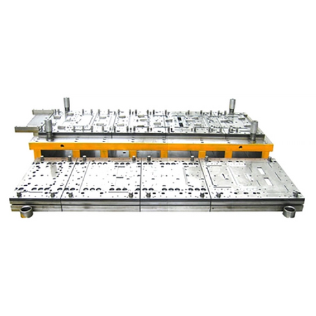
For a process overview, see KINGLAN’s guide to how transfer die stamping works. Its stamping die range covers single-stage, transfer, and progressive tooling.
Start with a proposed station layout and the loads that occur during the stroke. Verify usable press force at the forming position, energy at the intended speed, and permissible off-center loading. Several stations can apply load at different locations on the same stroke. A station-by-station load estimate helps the team check the combined demand and how it is distributed across the press.
Confirm usable bed and slide dimensions, die height, stroke, station pitch, and access for loading, unloading, and die changes. For a retrofit, share the exact press model and available drawings. Also identify any existing cushion, ejector, blank feeder, or controls that the new tooling must work with.
Review the path as the transfer mechanism grips, lifts, advances, lowers, and releases the workpiece. Check for interference between the grippers, part, punches, dies, and guides. Include changes in part height after drawing, movement as the part is released, and the position of any features that could catch on the tooling.
Define how the line will detect a missing part, a mislocated part, or a double blank where applicable. Agree on how the system will stop and how operators will clear the affected stations and restart. KINGLAN lists a two-dimensional manipulator for multistation press lines. Confirm the motion and gripping arrangement against your station layout before specifying equipment.

Ask each supplier to quote against the same annual volume, batch size, part tolerances, and operating assumptions. Include the die, transfer equipment, blank preparation, material losses, setup labor, maintenance, and expected downtime. Use accepted output over the same production period so a higher advertised stroke rate does not distort the comparison.
For example, suppose the transfer option adds $30,000 in upfront tooling and automation cost but saves an estimated $0.15 per accepted part in recurring production costs. Under those assumptions, it recovers the additional investment after 200,000 accepted parts. Recalculate if the two routes produce different scrap rates, maintenance costs, or changeover times. This is a calculation example for comparing proposals.
Include the following in your request for quotation:
Part and material: 2D drawing, 3D model if available, sheet grade, thickness range, finish, and cosmetic surfaces.
Production requirements: Annual demand, typical batch size, target accepted parts per hour, and planned changeover frequency.
Existing equipment: Press model, bed and slide dimensions, stroke, available die height, and installed feeding or transfer equipment.
Quality requirements: Critical dimensions, burr limits, allowable gripper marks, and inspection locations for thinning where relevant.
Trial requirements: Representative production blanks, agreed run duration, measurement frequency, and acceptance criteria for output and defects.
During the trial, measure accepted parts per hour alongside press speed. Log transfer faults, restart scrap, and recurring defects by station. A trial should show whether the proposed line can maintain part quality and restart reliably under the conditions that matter in production.
It is worth choosing when independent part handling solves a specific problem with drawing, access, location, or material utilization, and the trial supports the expected production cost and output. If a stable strip carries the part through every operation efficiently, progressive stamping can remain a strong option.
Yes, especially when separate blanks need to move through drawing, redrawing, and finishing operations. Confirm draw feasibility and establish reliable gripping and locating points for each intermediate shape.
Material savings depend on the actual blank and strip layouts. Compare carrier and strip scrap with blanking and trimming scrap, and include startup losses and rejected parts.
It may be possible after a compatibility review. Check die space, usable force and energy at the required speed, off-center load limits, transfer clearance, and the controls needed to synchronize the press with the handling system.
There is no universal threshold. Compare the additional investment with recurring savings per accepted part, then check whether expected lifetime demand and batch sizes support the payback.
Planning a multistage stamping project? Discuss your transfer die application with KINGLAN. Share the part drawing, material grade and thickness, annual volume, and existing press details. If you already run the part, include the operation that limits output or causes the most scrap.


