
Views: 0 Author: Site Editor Publish Time: 2026-10-12 Origin: Site


In high-volume metal stamping, engineering perfection dictates success. Minor oversights compound into severe production bottlenecks. A tooling failure at 100,000 strokes per hour destroys margins, damages presses, and halts supply chains. Bridging the gap between theoretical CAD models and physical press realities remains a constant challenge on the shop floor. Decision-makers must evaluate whether a proposed progressive die design accounts for dynamic forces, simultaneous operations, continuous metal strip feeding, and long-term maintenance before cutting steel. This checklist provides a rigorous framework for evaluating tooling proposals. By auditing strip layouts, station sequencing, material selection, and sensor integration, engineering teams can validate viability. You can select manufacturing partners capable of delivering millions of flawless cycles without unexpected downtime.
Strip Layout Dictates Profitability: Optimizing material utilization and progression accuracy upfront prevents excessive scrap costs and guarantees continuous strip stability throughout the die.
Simultaneous Execution is Non-Negotiable: Sequential operations must be engineered to balance cutting and forming forces simultaneously in a single stroke, preventing uneven die wear and press deflection.
Sensor Integration Mitigates Catastrophe: High-volume runs require integrated, in-die sensors for misfeed detection and slug-pull prevention to protect the tool from self-destruction.
Maintenance Accessibility Defines Uptime: A superior progressive die design utilizes modular, quick-change inserts for high-wear components, drastically reducing downtime during routine sharpening.
Table of Contents
The strip layout forms the foundation of any stamping operation. Evaluation focuses on maximizing material utilization while maintaining enough carrier web strength to feed the continuous metal strip accurately. A flawed layout compromises the entire production run, causing feeding issues and dimensional instability.
Raw material represents the largest ongoing expense in stamping. Engineers calculate optimal pitch and width to minimize skeleton scrap without weakening the carrier. Evaluating nesting strategies against the cost of wider coil stock requires hard math. Double-row layouts or interlocking profiles drastically reduce waste when stamping high-volume complex metal parts. You must analyze grain direction requirements. Forming across the grain prevents cracking in high-strength steels, even if it means sacrificing a few percentage points of material utilization. The layout must balance material savings against the physical limits of the metal.
Selecting the appropriate carrier type depends on part geometry. Central carriers provide stability for symmetrical parts, allowing even material flow. Single-edge or double-edge carriers allow for aggressive side-action forming and cam piercing. Designing stock lifters correctly keeps the strip perfectly level during advancement. This prevents binding, distortion, or feeding jams. Spring-loaded or nitrogen-driven stock lifters must provide enough upward force to clear the die matrix without inducing strip vibration. If the strip bounces during the feed cycle, the pilot pins will miss their targets, causing a misfeed.
The progression pitch dictates the exact distance the material moves forward during each press cycle. Calculating this dimension requires factoring in the physical size of the blank, the width of the connecting web, and the required clearance between stations. If the pitch is too tight, the web will tear under tension. If it is too loose, material waste skyrockets. Pilot holes must be punched in the very first station. These holes engage with bullet-nosed pilot pins in subsequent stations to pull the strip into perfect alignment before the cutting punches make contact. Sizing the pilot holes correctly ensures the strip can be located precisely without distorting the edges of the hole.
Engineering the layout to require minimum strip lift allows faster press speeds. Excessive lift forces the press to operate with a longer stroke, limiting strokes-per-minute efficiency. Validate that the die stroke accommodates part clearance without excessive over-travel. Keeping the progression tight ensures maximum efficiency and reduces wear on press bearings. You must also account for the stretch web. When drawing or forming deep features, the carrier web must flex and stretch without snapping. Incorporating expansion loops in the carrier design absorbs this material draw, keeping the overall pitch distance constant.
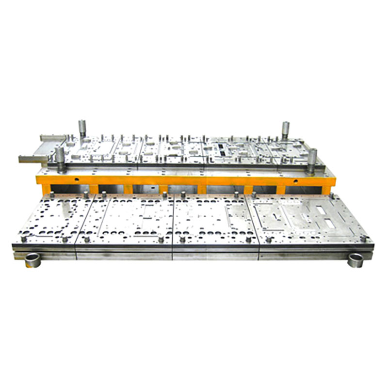
Each station in a Progressive Die performs its operation without compromising strip integrity. Complex metal parts require flawless synchronization to maintain dimensional accuracy.
Distribute heavy tonnage operations across the die length. This prevents off-center loading on the press ram. Off-center loading causes ram deflection, leading to premature die wear and uneven part thickness. Utilizing staggered punch lengths reduces initial impact shock. Stepping punches by a fraction of the material thickness minimizes acoustic noise and protects press bearings from massive tonnage spikes. When multiple punches hit the material simultaneously, the snap-through force can damage the press frame. Staggering the punch lengths by just a few thousandths of an inch breaks up this force into manageable increments.
High-strength steels possess significant material memory. Evaluating the design for over-bending stations or coining operations counteracts this natural elasticity. Reviewing Finite Element Analysis data validates springback compensation strategies before cutting steel. Relying on trial and error during the tryout phase delays production launches. You must design the forming stations with adjustable cam blocks or shimmable inserts. This allows toolmakers to fine-tune the over-bend angle on the press floor without pulling the entire tool out of the machine.
The stripper plate holds the material flat against the die block while the punches retract. Without a robust stripper plate, the material would lift with the punches, destroying the carrier web and causing a massive jam. Engineers must calculate the exact stripping force required based on the total cutting perimeter and the shear strength of the material. Heavy-duty coil springs or self-contained nitrogen gas cylinders provide this force. Nitrogen springs offer a more compact footprint and deliver full force upon initial contact, making them superior for high-strength materials. The stripper plate also acts as a secondary guide for slender piercing punches, preventing them from deflecting and snapping under heavy side loads.
Ensure adequate draft angles and clearance in die cavities. This facilitates reliable scrap shedding. Scrap retention, known as slug pulling, occurs when scrap adheres to the punch and retracts into the die. This destroys the tool on the next stroke.
Incorporate shear angles on the face of the piercing punches to break the suction of the oil film.
Install spring-loaded ejector pins inside the center of the punches to physically push the slug down.
Use bell-mouthed die buttons that widen slightly below the cutting land to prevent slugs from stacking up.
Integrate targeted air blasts timed with the press stroke to blow scrap out of the cutting zone.
Apply vacuum systems under the die shoe to actively pull lightweight slugs down the scrap chute.
High-volume production demands tooling materials that resist wear, galling, and fatigue. The upfront cost of premium materials offsets extended maintenance intervals.
Specifying tungsten carbide for high-impact punches is mandatory in ultra-high-volume runs. Carbide offers exceptional wear resistance but lacks toughness to handle severe lateral deflection. Selecting appropriate tool steels based on toughness ensures tool longevity. You must match the tooling material to the specific failure mode of that station. If a punch is chipping, it needs more toughness. If it is losing its edge quickly, it needs more wear resistance.
Tooling Material | Primary Characteristics | Ideal Application in Progressive Dies |
|---|---|---|
D2 Tool Steel | High carbon, high chrome. Good wear resistance. | Standard blanking and forming stations for moderate volumes. |
M2 High-Speed Steel | Excellent toughness and wear balance. | Punches subjected to high impact and moderate lateral forces. |
CPM-10V | Powder metallurgy. Extreme wear resistance. | High-wear cutting matrices stamping abrasive materials. |
Tungsten Carbide | Maximum hardness. Brittle under side loads. | Ultra-high-volume straight piercing and blanking punches. |
Evaluating Physical Vapor Deposition coatings reduces friction. Coatings like TiN, TiCN, and TiAlN are highly effective when stamping stainless steel or aluminum. These metals naturally tend to cold-weld to bare tool steel, a process known as galling. Verifying heat treatment specifications ensures core toughness is maintained alongside surface hardness. A punch with a hard surface but a brittle core shatters under production speeds. Cryogenic treatment after the initial quench and temper cycle stabilizes the microstructure of the steel. This prevents dimensional changes in the tooling components over time and increases overall fatigue life.
Operating at high speeds without continuous monitoring presents operational risks. The design must natively incorporate sensor technology to halt the press instantly upon detecting an anomaly.
Integrating proximity sensors or laser optics verifies the continuous metal strip has advanced to the exact micro-millimeter pitch. Utilizing pilot pins with built-in sensors detects if the strip is misaligned before the die closes. If the pilot pin cannot enter the pilot hole fully, the sensor sends a fault signal to the press control. This triggers an emergency stop within milliseconds, preventing the die from smashing half-formed parts.
Integrating dozens of sensors into a single tool requires a meticulously planned wiring strategy. Loose wires dangling from the upper shoe will inevitably be severed by moving components or crushed by rogue scrap metal. Engineers must design dedicated channels milled directly into the die shoe to route sensor cables safely. Consolidating all sensor connections into a heavy-duty, sealed junction box mounted on the side of the tool simplifies the setup process. When the tool is loaded into the press, the operator only needs to connect a single multi-pin umbilical cable to interface the tool with the press control system. This eliminates wiring errors and drastically reduces changeover time.
Designing optical or acoustic sensors confirms the final part has successfully separated from the carrier. A part left in the die block causes severe damage on the subsequent stroke. Monitoring scrap chutes prevents backups. If slugs stack up in the chute, they eventually crush the die matrix and shatter piercing punches. Piezoelectric tonnage monitors installed in the press frame track the force of every stroke. If a punch breaks or a slug pulls, the tonnage signature changes instantly. The monitor detects this deviation and stops the press before the next cycle.
Every tool eventually requires sharpening and routine maintenance. The design must allow toolmakers to service the die quickly without removing the entire shoe from the press.
Evaluating the use of segmented die blocks and punch inserts allows maintenance teams to swap out worn components in minutes. Ensuring inserts are keyed or doweled guarantees foolproof, repeatable alignment. Toolmakers should not need to indicate or manually align cutting components during a mid-run changeover. Modular design transforms a multi-hour repair into a quick pit stop.
The alignment between the upper and lower die shoes relies entirely on the guide pins and bushings. For high-speed operations, standard solid bronze bushings generate too much friction and heat, leading to thermal expansion and binding. Specifying pre-loaded ball-bearing guide pins eliminates this issue. Ball-bearing systems provide zero-clearance alignment, ensuring the punches enter the die matrix perfectly centered every single stroke. This tight alignment is critical when working with thin materials that require extremely tight cutting clearances. Engineers must also specify the correct pin length so the guide pins remain fully engaged in the bushings before any punches contact the material.
Verifying that the design includes adequate sharpening life on all cutting components extends the total lifespan. Standardizing shim plates allows technicians to easily restore punch and die heights after maintenance grinding. When a punch is ground down by a few thousandths of an inch, a corresponding shim must be placed behind it to maintain the exact forming depth. Design the stripper plate with removable windows. This gives toolmakers direct access to the piercing punches without having to unbolt the entire heavy stripper assembly from the upper shoe.

Selecting a tooling partner requires looking beyond the CAD file. You must assess their validation processes, engineering rigor, and manufacturing capabilities.
Requiring kinematic simulations and forming feasibility studies proves the design works in a virtual environment before build. Finite Element Analysis predicts material thinning, tearing, and springback. Tooling vendors who skip simulation rely on outdated trial-and-error methods. This leads to endless tryout loops, missed delivery dates, and tools that never quite run at the quoted speed. Demand to see the simulation reports for the most complex forming stations. Look for thinning percentages that exceed the material's safe limits.
Validating the vendor's logic is necessary. Did they objectively analyze whether the part geometry and volume justify a progressive setup? Sometimes a transfer die offers better dimensional control for deep-drawn features that must be separated from the strip early. A competent partner recommends the right process based on physics and production volume. They will calculate the reverse tonnage limits of your specific presses to ensure the tool won't damage your equipment.
Reviewing the vendor's in-house press capabilities for die tryouts under true production speeds is mandatory. Jogging a press slowly does not replicate dynamic forces, heat generation, and scrap shedding dynamics of a 100-stroke-per-minute run. Establishing strict FAI protocols, including Process Capability Index requirements, ensures the tool produces parts within tolerance consistently. The vendor must run a continuous strip of at least several thousand parts without stopping to prove the scrap shedding and feeding dynamics are stable.
Audit your current tooling proposals against this layout and sensor integration checklist to identify potential failure points before cutting steel.
Request kinematic simulations and FEA reports from your tooling vendors to validate springback compensation and forming feasibility.
Standardize sensor integration requirements across all future high-volume die builds to protect your press assets from catastrophic crashes.
Implement modular insert strategies for high-wear components to reduce maintenance downtime on the press floor.
A: Standard lead times range from 8 to 16 weeks. The exact timeline depends heavily on part complexity, the number of stations, and the integration of in-die sensors. Advanced tryout phases, including full-speed production simulations and FAI adjustments, extend the schedule but ensure long-term reliability on the shop floor.
A: Progressive dies handle high-speed, continuous coil feeding of flat or moderately formed complex parts. Transfer dies are required for deep drawing or parts that must be separated from the strip early. This allows the part to move between independent stations without the restriction of a continuous carrier web.
A: Industry benchmarks typically aim for 70% to 85% material utilization. Part nesting strategies heavily impact this metric. While higher utilization reduces raw material waste, engineers must ensure the remaining skeleton web retains enough strength to feed accurately through the press without distorting or buckling under tension.
A: Engineers use over-bending stations, coining operations, and FEA simulations to predict and counteract the natural elasticity of high-strength metals. By intentionally bending the material slightly past the target angle, the metal relaxes into the precise dimensional tolerance required immediately after it exits the forming station.
A: The most frequent causes of failure include slug pulling, material misfeeds, galling, and fatigue failure. Unbalanced cutting forces cause severe press deflection. This leads to shattered punches, damaged die matrices, and excessive wear on press bearings if not properly mitigated during the initial engineering phase.
A: Pilot sensors and ejection monitors continuously track the strip position and part exit. If a misfeed occurs or a part fails to eject, the sensors communicate with the press control to trigger an emergency stop within milliseconds. This halts the ram before it closes on an obstruction, preventing tool crashes.



