
Views: 0 Author: Site Editor Publish Time: 2026-10-12 Origin: Site


Unplanned press downtime wrecks production schedules. Tooling degradation directly escalates per-part manufacturing costs. High-volume manufacturing demands reliable equipment to maintain profitability. Premature tool failure presents a massive operational hurdle on the shop floor. Abrasive wear destroys punch edges rapidly. Adhesive wear, commonly known as galling, causes severe material transfer. Edge chipping ruins part quality and halts production. These issues compound heavily when stamping demanding materials. Advanced High-Strength Steels (AHSS) and aluminum push conventional tooling to its absolute limits.
Extending stamping die life is never a reactive maintenance chore. It requires a highly engineered, proactive approach. You must systematically evaluate metallurgy, surface engineering, and structural die design. Press dynamics and rigorous operational handling play equally critical roles. We will explore practical strategies to maximize tooling longevity and stabilize your stamping operations.
Material and Metallurgy: Upgrading from conventional tool steels to Powder Metallurgy (PM) or carbide substrates significantly delays abrasive wear and edge breakdown.
Surface Engineering: Applying the correct PVD or CVD coating (e.g., TiCN, AlTiN) mitigates adhesive wear and reduces the coefficient of friction, directly extending the maintenance interval.
Clearance and Alignment: Precision punch-to-die clearances and rigid press alignment are non-negotiable prerequisites; advanced materials cannot compensate for poor mechanical guidance.
Scrap Control and Dynamics: Proper slug shedding design and consistent stripper pad pressure are critical to preventing catastrophic double-hits.
Predictive Maintenance: Transitioning from run-to-failure to sensor-driven, stroke-count-based maintenance prevents catastrophic tool damage and preserves the die's structural integrity.
Table of Contents
Identifying the root causes of premature stamping mold damage is essential for improving tool life and reducing maintenance costs. Common factors include improper clearance, excessive loading, tooling misalignment, unsuitable materials, and inadequate lubrication. Accurate failure analysis helps manufacturers select effective corrective measures.
Root Cause Analysis (RCA) helps identify why stamping dies fail prematurely. Methods such as the 5 Whys, Ishikawa diagrams, and microscopic inspections can reveal wear patterns, fatigue cracks, and material defects. Engineers should examine damaged components, press tonnage records, material properties, and machine alignment to distinguish tooling defects from equipment-related problems.
Abrasive wear occurs when hard particles or workpiece materials gradually remove metal from cutting surfaces, causing dull edges and excessive burrs. Adhesive wear (galling) results from friction and material transfer between the workpiece and the metal stamping die. Proper lubrication, suitable tool materials, and surface coatings help minimize both wear mechanisms.
Micro-chipping and fatigue cracking result from repeated impact loads, excessive stress, or unsuitable tool steel properties. Brittle cutting edges may chip, while insufficient material strength can cause deformation or cracking. Optimizing heat treatment, edge geometry, and tool steel selection helps improve impact resistance and extend die service life.
Workpiece material properties significantly influence stamping die wear. Advanced High-Strength Steel (AHSS) and Ultra-High-Strength Steel (UHSS) generate higher cutting forces and tooling stress, while aluminum alloys are more susceptible to material adhesion and galling. Matching tooling materials, coatings, and lubrication to the workpiece helps prevent premature failure.
Selecting the right stamping die steel requires balancing hardness, wear resistance, toughness, and manufacturing costs. Material selection should reflect the primary failure mechanism, stamping conditions, and expected production volume.
Conventional tool steels, such as D2 and A2, provide cost-effective wear resistance for general stamping applications. Powder Metallurgy (PM) tool steels, including CPM 10V and Vanadis 4 Extra, feature finer, more uniform carbide structures that can improve wear resistance and resistance to edge chipping. PM steels are particularly suitable for demanding applications involving abrasive materials and high production volumes.
Material Grade | Manufacturing Process | Wear Resistance | Impact Toughness | Primary Application |
|---|---|---|---|---|
A2 | Conventional Ingot | Low | High | Low-volume, light forming, mild steel. |
D2 | Conventional Ingot | Moderate | Low | Medium-volume, standard cutting. |
CPM 10V | Powder Metallurgy | High | Moderate | High-volume, abrasive materials, AHSS. |
Micro-Grain Carbide | Sintering | Extreme | Very Low | Extreme volume, electrical steel, rigid presses. |
Tungsten carbide inserts provide extreme wear resistance. They outlast PM steels by massive margins in abrasive applications. Carbide is ideal for high-speed stamping of electrical laminations or stainless steel. It maintains a sharp cutting edge for millions of strokes. Many high-speed motor core dies rely exclusively on carbide components.
However, carbide comes with severe trade-offs. It has a high initial material and machining cost. More importantly, carbide is extremely brittle. It possesses virtually no impact toughness. Using carbide requires superior press rigidity. Any lateral deflection or angular misalignment will instantly shatter a carbide punch. You must ensure perfect mechanical guidance before upgrading to carbide.
Proper heat treatment is non-negotiable. The substrate hardness must support subsequent surface coatings. If the tool steel is too soft, it will deform under the coating. This causes the hard coating to crack and flake off, known as the eggshell effect. Strict adherence to austenitizing and tempering temperatures is mandatory. Always request a certified heat treatment chart from your vendor.
Deep cryogenic treatment further enhances tooling metallurgy. After the initial quench, the steel is cooled to roughly -300°F (-184°C). This extreme cold converts retained austenite into harder, more stable martensite. Cryogenic processing relieves internal residual stresses. It significantly enhances dimensional stability and improves overall wear resistance. Tools subjected to cryogenic processing hold their edge much longer in high-impact applications.
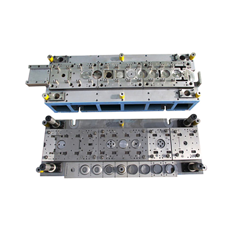
Surface coatings and treatments improve stamping die wear resistance, reduce friction, and extend tooling service life. Selecting the right coating depends on the workpiece material, operating temperature, and primary wear mechanism.
Physical Vapor Deposition (PVD) applies thin, wear-resistant coatings at relatively low temperatures, helping preserve tooling dimensions and making it suitable for precision punches and dies. Chemical Vapor Deposition (CVD) generally uses higher processing temperatures and can produce thicker, highly durable coatings, but may require additional heat treatment or finishing to maintain dimensional accuracy.
TiN, TiCN, and AlTiN coatings provide different levels of wear resistance and thermal protection. TiN is a cost-effective choice for general stamping, TiCN offers greater hardness and abrasion resistance for demanding materials, and AlTiN provides excellent high-temperature stability for applications involving substantial friction and heat. The optimal coating depends on material compatibility and stamping conditions.
Coating Type | Hardness (HV) | Friction Coefficient | Best For |
|---|---|---|---|
TiN | ~2300 | 0.40 | General purpose, mild steel, low cost. |
TiCN | ~3000 | 0.20 | Stainless steel, abrasive wear resistance. |
AlTiN | ~3300 | 0.35 | AHSS, high heat, dry machining/stamping. |
DLC (Diamond-Like Carbon) | ~2500 | 0.10 | Aluminum stamping, extreme anti-galling. |
Nitriding improves the surface hardness and wear resistance of stamping dies while maintaining a tough core. It helps reduce galling and surface damage, particularly on large forming components. Combining nitriding with PVD coatings provides additional surface protection for demanding stamping applications.
Proper punch-to-die clearance reduces burr formation, friction, and premature tooling wear. Clearance should be selected based on material thickness, strength, and stamping requirements. Insufficient clearance increases friction and stripping force, while excessive clearance may cause rough edges and dimensional defects. Testing helps determine the optimal setting.
Effective slug control prevents punched scrap from returning to the die surface and damaging tooling. Proper die clearance, relief angles, and suitable slug-retention or ejection mechanisms help ensure reliable scrap removal. These features reduce double-hit risks, protect punches, and improve production stability.
Stripper pads hold sheet metal securely during punching and remove material from the punch during withdrawal. Consistent stripper pressure prevents lateral punch movement and uneven loading. Properly selected coil springs or nitrogen gas springs help maintain reliable stripping performance and reduce tooling damage.
Punch edge preparation improves cutting-edge durability and coating performance. Controlled edge honing creates a small radius that helps reduce micro-chipping and premature wear. The appropriate radius depends on the workpiece material, cutting clearance, and tooling requirements.
Precision guiding systems maintain accurate punch-to-die alignment during stamping. Guide pins, bushings, wear plates, and heel blocks help control lateral forces and prevent tooling misalignment. Proper guidance reduces uneven wear, improves dimensional accuracy, and extends die service life.
Press tonnage and frame rigidity directly affect stamping accuracy and tooling durability. Excessive ram or bed deflection can cause uneven clearance, tool wear, and punch breakage. Selecting a press with sufficient capacity, structural stiffness, and appropriate shock control helps maintain stable production.
Stamping lubricants reduce friction, heat, and material adhesion during forming operations. Straight oils, water-soluble lubricants, and suitable Extreme Pressure (EP) additives offer different performance advantages. Lubricant selection should match the sheet metal, forming pressure, and operating conditions to minimize galling and tool wear.
Automated lubrication systems provide consistent lubricant distribution during stamping. Programmable spray systems control application timing and quantity, reducing dry contact, excess oil consumption, and operator variability. Proper lubrication improves forming consistency and helps extend tooling maintenance intervals.
In-die sensors and acoustic monitoring systems help detect stamping abnormalities before serious tooling damage occurs. Sensors can monitor material feeding, stripping force, and unusual cutting vibrations. Early detection of slug pulling, punch wear, or misalignment reduces unexpected downtime and supports preventive maintenance.
Regular punch and die sharpening maintains cutting quality and prevents excessive edge wear. Maintenance intervals should consider stroke count, burr height, and tooling condition. Proper grinding, cooling, and shimming help preserve tool hardness, restore cutting geometry, and maintain consistent stamping performance.
Standardized die handling and storage procedures help prevent accidental damage, corrosion, and setup errors. Use appropriate lifting equipment, verify shut height and press settings, and apply suitable rust protection during storage. Consistent operating procedures improve tooling safety, reliability, and readiness for production.
Tooling maintenance records support predictive maintenance and continuous improvement. Track stroke counts, sharpening operations, component replacements, and die adjustments to identify recurring problems. Analyzing this information helps optimize maintenance schedules, evaluate tooling upgrades, and reduce long-term production costs.
Extending tooling life demands a comprehensive, engineered strategy. Upgrading tool steel grades is entirely ineffective if press alignment, scrap shedding, and clearances remain flawed. You must address the mechanical foundation first.
To immediately stabilize your stamping operations, implement these actionable steps:
Conduct a rigorous failure analysis on your highest-maintenance die to identify the exact wear mechanisms.
Audit and correct press parallelism, bed deflection, and internal die guiding systems before investing in new materials.
Redesign slug clearance channels and install active ejector pins to eliminate catastrophic double-hits.
Upgrade lubricant chemistry to include targeted Extreme Pressure (EP) additives applied via automated spray systems.
Transition to a stroke-count-based predictive maintenance schedule to sharpen tools before severe edge degradation occurs.
A: Average life varies drastically based on material and design. A conventional D2 die stamping mild steel might run 100,000 strokes between sharpenings. A carbide die stamping thin electrical steel can exceed 2 million strokes. Stamping AHSS significantly reduces these intervals. Baseline expectations must be set per specific application.
A: Tight clearance increases friction, causing rapid heat buildup and severe galling. Loose clearance forces the material to bend rather than shear, accelerating edge rounding and creating large burrs. Precise clearance minimizes friction while ensuring a clean fracture, directly extending tooling longevity.
A: Coating flaking, or the eggshell effect, occurs when the tool steel substrate is too soft to support the hard PVD layer. Under high stamping pressure, the substrate deforms, causing the rigid coating to crack and detach. Proper heat treatment or pre-nitriding is required to support the coating.
A: It is generally not recommended. While carbide offers extreme wear resistance, it is highly brittle. AHSS requires massive tonnage and generates significant shock and vibration. This impact loading typically shatters carbide punches. Powder Metallurgy (PM) steels offer a better balance of toughness and wear resistance for AHSS.
A: Coil springs lose force over time due to metal fatigue, resulting in uneven stripper pad pressure. This uneven pressure causes lateral punch deflection and breakage. Nitrogen gas springs provide constant, uniform pressure throughout their lifecycle, ensuring the punch remains perfectly aligned during stripping.
A: Slug pulling is primarily caused by a vacuum forming between the punch face and the scrap, or insufficient draft angle in the die button. It is exacerbated by heavy lubricants. Using air ejector pins, vacuum blocks, or specialized punch face geometry breaks the suction and forces the slug down.



