
Views: 0 Author: Site Editor Publish Time: 2026-08-24 Origin: Site


The transition from mechanical feeding systems to programmable automation marks a critical inflection point for stamping operations. It directly impacts material yield and part precision. Selecting the wrong feeding equipment leads to material slippage and synchronization failures with the power press. This mismatch causes increased scrap rates and significant production downtime. A misalignment between feeder capacity and material yield strength often results in premature mechanical failure. This guide provides a technical framework for evaluating an NC servo feeder. We focus on material constraints, press compatibility, production volume, and overall line integration. You will learn how to match feeder specifications to your exact stamping requirements. We will explore key differences in release mechanisms, material thickness capacities, and PLC synchronization techniques.
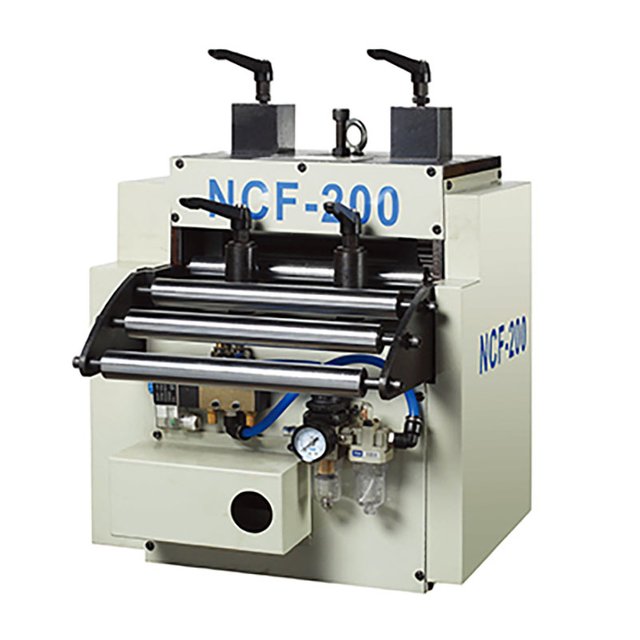
Material Dictates the Machine: Feeder selection must begin with maximum material thickness, width, and weight. The industry typically categorizes NC servo feeders into three types: thin, medium, and thick plate (up to 4.5mm+).
Speed vs. Accuracy Trade-offs: High-speed stamping requires specific servo drive capabilities and mechanical release mechanisms to maintain tight feeding accuracy tolerances without material distortion.
Integration is Critical: Seamless PLC synchronization between the NC servo feeder and the specific type of power press (mechanical, hydraulic, or servo) is mandatory for complex stamping patterns and variable cycle choices.
Application-Specific Configurations: General power press feeding relies on standard NC servo feeders, while specialized operations require zigzag feeders for optimal blanking yield or high-speed models for dedicated, long-run production.
Table of Contents
Traditional mechanical feeding systems rely on an eccentric cam mounted to the press crankshaft. This cam connects via a pitman arm to an overrunning clutch on the feeder. Every time you need to change the feed length, an operator must manually adjust the throw of the eccentric cam using wrenches. This process requires trial and error, wasting valuable production time. Furthermore, the mechanical clutch wears down over millions of cycles, introducing backlash and causing inconsistent feed lengths. Operators constantly chase the pitch, making micro-adjustments to prevent die crashes.
An NC servo feeder completely severs this rigid mechanical link. It utilizes a standalone AC servo motor coupled directly to the lower feed roll via a precision planetary gearbox or a zero-backlash timing belt. The digital control system eliminates manual pitch adjustments entirely. Operators input the required feed length via a touchscreen interface, and the servo motor executes the command with exact repeatability. You can program complex, multi-stage feeding patterns that a mechanical feeder simply cannot perform.
Operational Metric | Mechanical Roller Feeder | NC Servo Feeder |
|---|---|---|
Feed Length Adjustment | Manual wrench adjustment on eccentric cam | Digital input via HMI touchscreen |
Changeover Time | 15 to 45 minutes | Under 1 minute (using saved recipes) |
Multi-Pitch Capability | Impossible (fixed stroke only) | Standard feature via PLC programming |
Wear Components | Overrunning clutch, brake, linkages | Minimal (sealed bearings, timing belts) |
Integration with Sensors | Difficult, requires external relays | Native integration with die protection systems |
A successful implementation transforms press room dynamics. Setup times drop from hours to minutes. You achieve zero-defect feeding with consistent accuracy. The equipment maximizes strokes per minute without causing material distortion. Coil line integration becomes seamless from the uncoiler straight through to the press. The entire system operates as a single, synchronized unit, communicating via standard industrial protocols.
Feeder selection relies heavily on the physical properties of the coil. You must evaluate the material thickness, width, and overall weight. Pushing a feeder beyond its rated capacity results in immediate slippage, motor faults, and damaged rollers. The industry divides feeding equipment into three distinct categories based on these dimensions.
Thin Sheet (0.1mm to 1.0mm): Optimized for delicate, high-speed applications like electrical contacts or motor laminations. These feeders use lightweight, hollow rollers to reduce rotating mass. This low inertia allows rapid acceleration and deceleration without buckling the fragile material.
Medium Plate (1.0mm to 3.2mm): The standard choice for general-purpose stamping. They balance speed and torque effectively. These units handle standard cold-rolled steel and aluminum coils found in most automotive bracket and appliance panel manufacturing.
Thick Plate (3.2mm to 4.5mm+): Requires heavy-duty structural reinforcement. High-torque servo motors drive the heavy coils. The frame utilizes thick steel side plates to prevent deflection under immense physical resistance. These units often feature alligator-style opening heads for easier threading of rigid stock.
You must assess material width and coil weight capacities. Compare these figures to the feeder's physical size. Factor in the specific material type. High-tensile advanced high-strength steel (AHSS) behaves differently than soft aluminum. It requires significantly more straightening force and grip pressure. Delicate surface finishes demand specific roller coatings. Polyurethane (PU) coated rollers or sandblasted matte finishes prevent surface marring on pre-painted, galvanized, or polished metals.
Calculate the required Strokes Per Minute (SPM) for your production runs. Match this figure directly to the servo motor capabilities. You must understand the relationship between feed length, press speed, and available feeding time. The feeder must complete its motion within the open portion of the press cycle, known as the feed window.
If a press runs at 60 SPM, one full stroke takes exactly 1.0 second. The die is only open for a portion of that stroke—typically from 270 degrees on the upstroke to 90 degrees on the downstroke. That creates a 180-degree feed window. The feeder has exactly 0.5 seconds to accelerate the material, reach top speed, decelerate, and stop precisely on pitch. Longer feed lengths require higher acceleration rates to finish within this same time window. High-speed operations demand low-inertia servo systems. The motor must reach maximum velocity instantly and stop without overshooting. Insufficient motor torque leads to sluggish feeding, causing the material to arrive late and resulting in severe die crashes.
Define the acceptable deviation for your stamped parts. A standard tolerance for precision stamping is ±0.02mm. Evaluate the role of closed-loop feedback systems. High-resolution encoders maintain accuracy over long runs. They monitor the exact position of the feed rollers, often generating hundreds of thousands of pulses per revolution.
The encoder sends real-time data back to the servo drive. The drive corrects minor discrepancies instantly. This prevents cumulative errors from ruining progressive die operations. Rigid mechanical construction also supports this precision. Any flex in the feeder frame, or backlash in the planetary gearbox, will negate the accuracy of the servo motor. You must ensure the mechanical drivetrain is rated for zero-backlash operation.
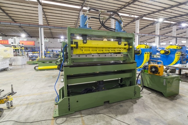
The release mechanism is a non-negotiable feature for progressive die stamping. Progressive dies use pilot pins to locate the strip precisely before the punches strike. If the feeder rollers remain clamped tightly on the material, the pilot pins fight the feeder. This elongates the holes in the strip and destroys part accuracy. The release mechanism momentarily lifts the upper feed roller a fraction of a millimeter. This allows the material to float into exact alignment just as the pilot pins engage.
Feature | Pneumatic Release | Mechanical Release |
|---|---|---|
Actuation Method | Air cylinder triggered by solenoid valve | Physical cam linked to press crankshaft |
Speed Limit | Slower (limited by air valve response lag) | High-speed (matches press SPM exactly) |
Setup Complexity | Simple, adjusted via PLC timing angles | Requires mechanical cam alignment on press |
Best Application | General stamping, speeds under 150 SPM | High-speed progressive dies, 200+ SPM |
Pneumatic release suits standard stamping and slower speeds. It works well for general-purpose applications. The initial setup is simpler because you control timing through the PLC using programmable cam switches. However, air valve response times limit the maximum speed. The inherent lag in compressed air systems causes the release to happen too late at high speeds. Mechanical release is essential for high-speed stamping. The press cam drives the release mechanism directly via a lever arm. This offers exact, instantaneous synchronization. It provides a faster pilot release for demanding progressive dies running at hundreds of strokes per minute.
Thick, rigid materials demand robust structural engineering. Upgraded gearboxes handle the increased load. Larger servo motors provide necessary torque to pull heavy coil stock from the loop pit. Reinforced straightening rollers prevent material bowing during the feed cycle.
These heavy-duty units feature thick steel side plates. They utilize heavy-duty spherical roller bearings to support the oversized feed rolls. The clamping force must be significantly higher to prevent slippage on thick gauge steel. Pneumatic cylinders on thick plate feeders are oversized to generate this required grip pressure. Some extremely heavy-duty models utilize hydraulic clamping cylinders instead of pneumatic ones to ensure the material cannot slip under heavy acceleration.
Evaluate two-axis movement for staggered blanking operations. Zigzag feeders move the material both forward (X-axis) and side-to-side (Y-axis). This optimizes the layout of circular or irregular blanks on the coil strip. The servo motors coordinate simultaneously to position the material for the next punch.
Calculate material yield improvements carefully. Circle and disc stamping operations, such as motor laminations or saw blade manufacturing, often see a 7% to 14% scrap reduction. The zigzag motion nests the blanks tightly together. This reduces the web width between punches. It maximizes the number of parts produced from a single coil, directly lowering raw material consumption.
You must evaluate integration differences across various press types. Traditional mechanical gap-frame presses require specific timing cams or rotary encoders mounted to the crankshaft to signal the feeder. Slower hydraulic presses need different handshake signals due to their variable stroke speeds and lack of a traditional rotating crankshaft. Highly programmable servo presses offer the most seamless integration but require advanced communication protocols.
Servo presses can adjust their stroke profiles dynamically, pausing at the bottom of the stroke or reversing direction. The feeder must communicate constantly with the press controller. This ensures the feed cycle only occurs when the die is fully open and clear. If the servo press enters a pendulum mode (short strokes without full rotation), the feeder PLC must track the exact ram position to avoid feeding into a closed die.
Evaluate HMI (Human-Machine Interface) usability. Operators need intuitive screens to input parameters quickly. Complex menus lead to setup errors. Ensure communication protocol compatibility between devices. The feeder PLC (often Mitsubishi, Siemens, or Allen-Bradley) must integrate with the press controls.
The feeder's drive must talk to the primary power press PLC without lag. Hardwired signals provide reliable timing for critical functions like "OK to Feed" and "Emergency Stop". Ethernet/IP or PROFINET connections handle recipe data, fault codes, and diagnostic information. Proper synchronization prevents the press from cycling if the feeder has not completed its move. You must wire the feeder's "Feed Complete" relay directly into the press's die protection circuit.
Configure feed timing carefully based on die requirements. Options include feed before press, press before feed, or intermittent operations. Feed before press is standard for most blanking operations. The material advances while the ram is at the top of the stroke. Press before feed is used when the material must remain stationary until the die engages, often seen in deep drawing operations.
Set up pilot release timing accurately for progressive dies. The rollers must open exactly when the pilot pins enter the material. They must close before the stripper plate releases the strip on the upstroke. Incorrect timing causes the pilot pins to stretch or tear the material holes, leading to immediate part rejection.
Assess physical space constraints in your facility. Measure the overall size of the unit on the press bed. Ensure it does not interfere with die changes, scrap removal chutes, or safety light curtains. Align the passline height perfectly with the die entry level. Most feeders include a mounting bracket with screw jacks, allowing for ±50mm of vertical passline adjustment to accommodate different die heights.
Synchronize speed with existing upstream equipment. Uncoilers and straighteners must match the feeder pace. They must maintain a consistent slack loop. If the straightener runs too slow, the feeder will pull the material tight, lifting it out of the loop pit and causing severe slippage. If it runs too fast, the material will drag on the floor. Utilize ultrasonic loop sensors or photoelectric eyes to control the straightener's variable frequency drive (VFD), keeping the material loop at a constant depth.

Programmable job memory saves countless labor hours. Recipe storage allows instant recall of previous setups. Operators simply select the part number from the HMI screen. The PLC automatically adjusts the feed length, speed, acceleration profiles, and even the motorized passline height on advanced models.
This replaces tedious manual mechanical adjustments. You eliminate the need for wrenches, dial indicators, and trial-and-error measurements. Rapid changeovers increase overall equipment effectiveness (OEE). The press spends more time stamping parts and less time sitting idle during die swaps. A competent operator can switch from one coil job to another in under two minutes.
Eliminating misfeeds directly improves material yield. Consistent feeding prevents partial stampings at the end of a coil. Optimizing blanking layouts maximizes raw material usage. The precision of the servo motor ensures every millimeter of the coil is utilized effectively, reducing the required edge trim allowance.
Accurate pilot release prevents material distortion. Distorted material often jams in the die, causing extensive scrap and requiring operators to manually cut and clear the tangled strip. Maintaining tight tolerances ensures the final stamped parts meet quality control standards on the first hit, eliminating downstream sorting and rework.
Evaluate the lifespan of critical components. Servo drives, timing belts, and feed rollers require regular inspection. Polyurethane rollers wear down over time and lose their grip, requiring periodic recoating. Steel rollers can develop grooves if running narrow, abrasive materials continuously. You must plan for roller regrinding in your preventative maintenance schedule.
Ensure the availability of spare parts before purchasing. Verify OEM technical support capabilities. You need access to troubleshooting assistance when electrical faults occur or when the servo drive throws an overcurrent error. Regular preventative maintenance, including greasing the gearhead and inspecting the encoder cables, keeps the servo system running at peak performance.
Material slippage ruins part accuracy immediately. It occurs when the rollers lack sufficient grip, when the acceleration is set too high, or when the material is covered in heavy stamping fluid. Camber involves the material bowing sideways as it enters the die, causing the strip to hit the die guides.
Specify the correct roller pressure for your material thickness. Utilize edge guides on the feeder entry to keep the material straight. Ensure proper upstream material straightening before the feeder. A good straightener removes coil set, making it easier for the feeder to push the material accurately. If running heavily oiled stock, specify sandblasted or matte-finish rollers to break the fluid surface tension and maintain grip.
High SPM operations push equipment to its limits. Pneumatic valves may fail to open and close fast enough. This causes the release mechanism to drag on the material. The servo motor may overheat if undersized for the required acceleration, leading to a following error in the drive.
Opt for mechanical release over pneumatic for high SPM applications. Implement strict encoder calibration protocols. Regularly verify timing signals between the press cam and the feeder PLC. Use an oscilloscope if necessary to check signal latency between the press rotary cam switch and the feeder input module.
Complex control systems intimidate untrained operators. Entering the wrong feed length causes immediate die crashes. Incorrect acceleration settings cause the material to buckle or slip. Bypassing die protection sensors to clear a fault often leads to catastrophic tooling damage.
Prioritize intuitive HMI systems with built-in error diagnostics. The screen should clearly display fault codes and troubleshooting steps. Establish mandatory OEM training during commissioning. Operators must understand the relationship between speed, feed length, and press timing. Implement password protection on the HMI to prevent unauthorized personnel from altering critical acceleration and timing parameters.
Audit your current press room bottlenecks by logging downtime attributed to manual mechanical feed pitch adjustments.
Calculate the required feed lengths and maximum strokes per minute for your heaviest progressive dies to size the servo motor correctly.
Request a proof-of-concept material test from shortlisted feeder manufacturers using your specific coil stock and required tolerances.
Measure the available press bed space and passline height to ensure physical compatibility before ordering the equipment.
For manufacturers looking to build or upgrade automated stamping lines, Kinglan provides press automation equipment and solutions designed to support a wide range of metal forming and stamping requirements. With experience in press machinery and automated feeding systems, Kinglan helps manufacturers integrate suitable equipment into their production lines to improve feeding accuracy, operational efficiency, and overall stamping reliability.
A: An NC servo feeder offers programmable flexibility and precision. It uses digital controls for rapid changeovers and complex, multi-stage feeding patterns. A roller feeder relies on mechanical linkages connected to the press crankshaft. It excels in dedicated, high-volume, continuous runs with fixed parameters but lacks the quick adaptability of servo-driven systems.
A: Start by matching the maximum material width and thickness category to the feeder's specifications. Measure the overall unit footprint to ensure it fits your press bed without blocking scrap chutes. Finally, verify that the feeder's passline height adjustment range aligns perfectly with your die heights and upstream straightening equipment.
A: A zigzag feeder utilizes two-axis movement to stagger punch locations. It is primarily used in circle or disc stamping operations, such as motor laminations. By alternating the feeding positions side-to-side, it maximizes material yield and significantly reduces scrap, often improving raw material utilization by up to 14%.
A: Yes, it can handle delicate surfaces easily. Standard steel rollers can be replaced with specialized polyurethane or rubber-coated rollers. These custom coatings provide the necessary grip for accurate feeding while preventing scratches, marring, or damage to pre-painted, galvanized, and sensitive polished materials.
A: Mechanical release mechanisms are driven directly by the press cam. This provides faster and more precise pilot release timing. It is absolutely necessary for high-speed progressive die stamping, where the slower response time and inherent lag of pneumatic air valves would cause material desynchronization and feeding errors.
A: Standard cycle choices include feed before press, press before feed, and intermittent feeding. Feed before press moves material before the ram descends. Press before feed actuates the die before advancing the coil. Intermittent operations allow custom timing based on specific progressive die and press requirements.



