
Views: 0 Author: Site Editor Publish Time: 2026-08-10 Origin: Site


Underestimating press tonnage leads to catastrophic equipment failure, broken tie rods, and shattered tooling, while overestimating results in unnecessary capital expenditure on oversized machines. Modern stamping involves complex variables—Advanced High-Strength Steels (AHSS), progressive die stations, and varying shear angles—making baseline theoretical calculations insufficient for safe, continuous production. Engineering teams face tight tolerances and demanding material properties every day on the shop floor. Relying on guesswork destroys machinery and halts assembly lines.
To protect equipment and ensure part quality, engineering and procurement teams must utilize a systematic approach to power press tonnage calculation, factoring in operation types, material properties, safety margins, and press energy curves. Accurate load evaluation prevents frame deflection and die damage. This guide breaks down the exact methodologies required to size your stamping operations correctly and keep your production running without interruption.
Table of Contents
The Baseline Formula: Cutting tonnage is fundamentally driven by the material’s shear strength, thickness, and total cut perimeter, but must be adjusted for tooling shear.
The 30% Rule: Industry standard dictates adding a minimum 30% safety margin to the total calculated tonnage before selecting a standard mechanical press size.
Force vs. Energy: Tonnage (force) is only half the equation; mechanical presses must also have the flywheel energy required to sustain that force through the necessary working distance.
Progressive Die Complexity: Total tonnage in progressive stamping must account for simultaneous operations, off-center loading, and snap-through shock (reverse tonnage).
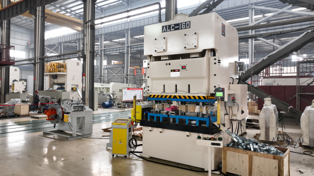
Operators must understand the critical distinction between required load and rated capacity. Required tonnage is the peak load demanded by the specific stamping operation. This force cuts, bends, or forms the metal part. The press tonnage rating is the maximum peak load the machine can safely deliver without structural damage. These two numbers are not interchangeable. A machine rated for 200 tons cannot continuously run a 200-ton required load without severe wear. You must calculate the required force accurately to match it against a properly de-rated machine capacity. Running a press at its absolute maximum rating daily guarantees premature component failure.
Exceeding the press capacity causes excessive bed and ram deflection. Metal frames bend under extreme pressure. This deflection leads to premature die wear and out-of-tolerance parts. Punches misalign with dies during the stroke. The resulting friction dulls tooling instantly and causes severe galling on the cutting edges. Severe overloads cause catastrophic crankshaft failure. Tie rods snap under the immense tensile stress, turning a routine production run into a massive repair job. Accurate calculations keep the applied force well within the elastic limits of the press frame. This preserves die life, maintains strict part dimensions, and keeps the ram perfectly parallel to the bolster plate.
Blanking operations create sudden load releases. The punch builds massive pressure before the material finally fractures. This sudden fracture releases stored energy instantly. We call this snap-through shock or reverse tonnage. Uncalculated reverse tonnage destroys press bearings and connections. The ram violently jerks downward and then rebounds. This shockwave travels through the entire machine architecture, loosening bolts and cracking cast components. Calculating the forward cutting force helps predict the resulting reverse shock. Engineers can then implement dampening solutions to protect the equipment and extend the life of the press drive train.
Sizing a press accurately prevents the over-specification of equipment. Buying a 600-ton press for a 200-ton job wastes capital. Larger machines consume more floor space and require heavier foundations. They also draw more electrical power to spin massive flywheels. However, undersizing a press leads to constant breakdowns and lost production time. Accurate calculations ensure the machine is robust enough for the facility's heaviest planned jobs without wasting resources. You strike the perfect balance between machine capability and financial efficiency by knowing exactly how much force your parts actually require.

Different metals require vastly different cutting forces. Mild steel cuts easier than stainless steel. Aluminum requires less force than carbon steel. Advanced High-Strength Steels (AHSS) and Ultra High-Strength Steels (UHSS) demand massive tonnage. You must know the exact material grade. Shear strength dictates the cutting force. Engineers typically estimate shear strength at 70 to 80 percent of the material's ultimate tensile strength (UTS). Using the UTS instead of shear strength overestimates the required blanking force. Always verify the specific material certification before finalizing calculations, as coil properties vary between steel mills.
Material Type | Estimated Tensile Strength (PSI) | Estimated Shear Strength (PSI) |
|---|---|---|
Aluminum (5052-H32) | 33,000 | 20,000 |
Mild Steel (1018 Cold Rolled) | 64,000 | 45,000 |
Stainless Steel (304) | 73,000 | 55,000 |
AHSS (DP780) | 113,000 | 85,000 |
Material thickness shares a direct linear relationship with required cutting force. Doubling the material thickness doubles the required tonnage. Thicker materials also require more energy from the flywheel to push the punch through the metal. You must measure the maximum possible thickness tolerance. Sheet metal varies slightly from coil to coil. If a print calls for 0.125-inch steel with a +/- 0.010 tolerance, always use 0.135 inches in your calculations. This prevents unexpected overloads when a slightly thicker coil enters the feeder. Ignoring thickness tolerances is a common cause of unexplained press stalling.
The total shear length determines the overall resistance the punch meets. You must calculate the total perimeter for complex blank profiles. Measure every curve, notch, and straight edge. Add the circumferences of all internal pierced holes. A large part with a simple profile might require less tonnage than a small part with intricate cutouts. CAD software easily provides the exact perimeter length. Use this precise measurement rather than rough estimations to ensure accurate load predictions. Missing a few internal holes in your perimeter calculation throws off the entire tonnage requirement.
Tooling condition drastically alters the required force. Sharp punches shear metal cleanly and efficiently. Dull punches force the material to tear rather than shear. This tearing action increases the required tonnage significantly. Improper punch-to-die clearance also spikes the load. Too tight clearance causes secondary shearing, forcing the press to work twice as hard. Too loose clearance causes excessive bending before the fracture occurs, creating massive burrs and requiring more force to push the slug through the die matrix. Maintaining optimal clearance—typically 8 to 12 percent of material thickness for mild steel—keeps the actual tonnage aligned with your theoretical calculations.
Allowable tonnage depends on the tooling as much as the machine. A press might have a 100-ton capacity. However, individual punches have specific compressive yield limits. Slender punches will buckle and shatter long before the press reaches its maximum capacity. You must calculate the maximum allowable punch tonnage. Compare the required cutting force against the compressive strength of the punch material. Upgrade to high-speed steel or carbide punches if the load exceeds the yield strength of standard tool steel. A shattered punch destroys the die block and ruins the production run.
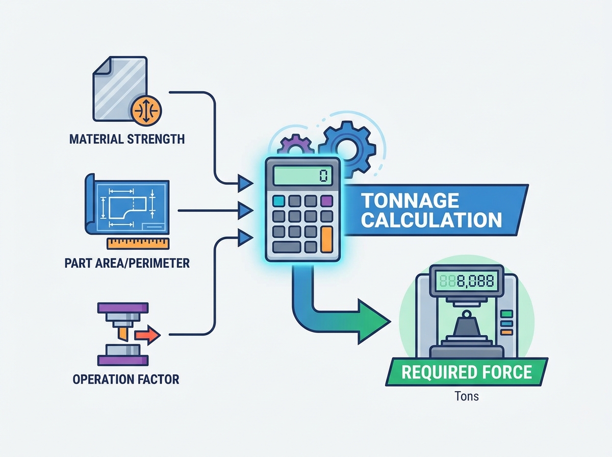
The core formula for cutting operations is straightforward. You multiply three specific variables. Tonnage equals Perimeter multiplied by Thickness multiplied by Shear Strength. You must convert the final number into tons by dividing by 2,000 (if using pounds). This baseline equation applies to any shape or profile. Ensure all measurements use the same unit system. Mixing inches and metric units causes massive calculation errors.
For example, calculating the tonnage for a 10-inch perimeter blank in 0.125-inch mild steel with a shear strength of 45,000 PSI looks like this: (10 × 0.125 × 45,000) / 2,000. The result is 28.12 tons. You then add your safety margin to this base number.
Shop floors often use a simplified formula for round holes in mild steel. You multiply the Punch Diameter by the Material Thickness. You then multiply that result by a constant of 80. This provides the required tons of pressure quickly. This shortcut only works for standard mild steel. Do not use this shortcut for stainless steel or aluminum.
Tooling shear reduces the peak tonnage. Stepping punches means making some punches shorter than others. They hit the material at different times. Adding angular shear to the die face also reduces the peak load. The punch cuts the material gradually like a pair of scissors. This distributes the cutting action over a longer portion of the stroke. It lowers the peak force but requires the exact same total energy from the flywheel.
Bending operations require different calculations based on the die type. V-bending formulas rely on the die opening width. We call this the V-die ratio. The required force depends on the material thickness squared, multiplied by the tensile strength, divided by the die opening. A wider V-die opening requires less tonnage but creates a larger inside bend radius. U-bending requires significantly more force than V-bending because the material drags along the die walls, creating massive friction. Wiping and edge flanging operations require specific tonnage calculations based on the flange length and material yield strength. Always account for the bottoming force if the die coins the radius to set the angle.
Draw force calculation predicts the load needed to pull a flat blank into a 3D shape. The formula uses the blank diameter, punch diameter, material thickness, and tensile strength. Drawing stretches and compresses the metal simultaneously. Deep drawing requires a blank holder or die cushion. The cushion holds the blank in place to prevent wrinkling as the metal flows into the die cavity. You must add 15 to 30 percent of the draw tonnage to account for this cushion force. Failing to add cushion tonnage leads to stalled presses and ruined parts.
Squeezing operations require the highest tonnage per square inch. Coining, embossing, and sizing force the metal to flow into tight die cavities. These operations demand massive pressure. They often require 3 to 5 times the material's compressive strength. The entire surface area under the punch experiences extreme load. You calculate the total surface area and multiply it by the specific coining pressure factor for that metal. Always size presses conservatively for coining applications to prevent frame damage. A slight over-adjustment on the ram during a coining operation will crack a press frame instantly.
Operation Type | Standard Formula / Guideline | Key Variables |
|---|---|---|
Blanking / Piercing | (Perimeter × Thickness × Shear Strength) / 2000 | Total cut length, material thickness, shear strength |
Mild Steel Hole (Shortcut) | Diameter × Thickness × 80 | Punch diameter, material thickness |
V-Bending | (Thickness⊃2; × Tensile Strength × Length) / V-Opening | Die opening width, tensile strength, bend length |
Deep Drawing | Draw Force + (15% to 30% Cushion Force) | Blank diameter, punch diameter, tensile strength |
Coining / Embossing | Surface Area × (3 to 5 × Compressive Strength) | Total squeezed area, material compressive limit |
Progressive dies perform multiple operations sequentially. The total die requirement equals the sum of all active stations. You must calculate the tonnage of each individual station separately. Calculate the piercing load. Calculate the forming load. Calculate the drawing and cutoff loads. Add all these peak loads together. This total represents the absolute maximum force the die could demand if all stations hit peak load simultaneously. This baseline sum is your starting point for progressive die evaluation. If you have a 5-station die with loads of 15, 0, 20, 40, and 10 tons, your baseline requirement is 85 tons before safety margins.
Uneven tonnage distribution creates severe risks in progressive dies. Heavy drawing at one end and light piercing at the other creates a tipping moment. The press ram tries to tilt. This ruins gib clearances and destroys die alignment. You must calculate the center of load for the entire die. Ensure this load center aligns closely with the centerline of the press ram. If the tipping moment exceeds the press's allowable off-center load limits, you must redesign the die layout. You can add dummy stations or shift the heavy operations closer to the center of the die shoe to balance the forces.
Engineers stagger punch lengths to reduce total peak tonnage. You alter the length of the punches by a distance equal to half or full material thickness. Station one finishes cutting just as station two begins. This prevents all stations from hitting peak tonnage simultaneously. Staggering cuts the required press tonnage significantly. It also reduces reverse tonnage shock. The press frame experiences a series of smaller loads instead of one massive impact. This extends both die and press lifespan. Proper staggering turns a 100-ton peak load into three separate 35-ton loads spread across the stroke.
Manual calculations leave room for human error. We recommend the use of digital tonnage calculators and forming simulation software. These tools accurately map out station-by-station loads. They simulate the entire stroke virtually. Finite Element Analysis (FEA) software predicts material thinning and exact force requirements. You can identify off-center loading issues before cutting any tool steel. Digital validation prevents costly mistakes and ensures the selected press can handle the dynamic forces of the progressive die. Relying on software validation is standard practice for complex automotive and aerospace components.

Theoretical calculations represent perfect conditions. Shop floors rarely offer perfect conditions. You must apply a strict safety factor. Calculate the total theoretical tonnage. Add a 30 percent safety margin to that figure. This accounts for material thickness variations, dull tooling, and dynamic friction. Once you have this final number, select the next standard press size above it. If your calculation plus 30 percent equals 180 tons, you select a 200-ton press. Never run a press at exactly 100 percent of its rated capacity. Running at maximum capacity leaves zero room for error when a punch dulls or a thicker coil enters the machine.
Tonnage limits apply differently across various press architectures. C-frame presses suffer from inherent angular deflection. The open front allows the frame to yawn under heavy loads. Straight-side presses feature a closed box frame. They resist deflection much better and handle off-center loads safely. Flat bed die cutting presses distribute force differently than traditional stamping presses. You must match the machine architecture to the specific demands of the die. Do not put heavy progressive dies in C-frame presses. The angular deflection will destroy the progressive die alignment and cause constant punch breakage.
Mechanical presses do not deliver full tonnage throughout the entire stroke. They are rated for full tonnage only at a specific distance above bottom dead center (BDC). This distance is usually between 1/16 inch and 1/4 inch above BDC. Drawing operations engage the material high up in the stroke. The available press capacity drops drastically at this height. A 200-ton press might only deliver 80 tons of force two inches above BDC. You must consult the manufacturer's tonnage curve chart to verify available force at the exact point of impact. Ignoring the tonnage curve is the primary reason presses stall during deep draw operations.
Force and energy are two different mechanical requirements. Tonnage is the physical strength to push the punch through the metal. Flywheel energy is the sustained power required to maintain that force over a specific distance. A press may have the physical strength to cut a part. However, it might lack the motor and flywheel energy to push through thick material or deep draws. If the operation drains too much energy, the flywheel slows down. The motor slips, and the press stalls midway through the stroke. Always verify flywheel energy capacity alongside tonnage ratings, especially for continuous high-speed stamping.
Advanced high-strength steels change all traditional rules. Stamping AHSS causes an exponential increase in required force. The material resists deformation aggressively. It also requires massive amounts of flywheel energy. Standard presses flex and stall when running UHSS parts. You must use specialized, high-rigidity press frames. These machines feature reinforced crowns, heavier beds, and oversized drive trains. Standard tooling also shatters under AHSS loads. You must upgrade to premium tool steels and advanced physical vapor deposition (PVD) coatings to survive the extreme friction and pressure generated by dual-phase and martensitic steels.
Reverse tonnage destroys machinery faster than forward overloads. Reverse tonnage limits typically sit at 10 to 20 percent of the forward press capacity. A 400-ton press can only handle 40 to 80 tons of snap-through shock. You must calculate the expected reverse load during the die design phase. Mitigation strategies are mandatory for heavy blanking. Install shock dampers or hydraulic dampening systems under the press bed. These devices absorb the downward energy release, protecting the press connections and bearings from catastrophic failure. Proper dampening extends the life of the press drive train by decades.
Operators must identify reverse tonnage on the shop floor immediately. Listen for loud snapping noises during the cutting stroke. Watch for excessive press vibration. If the floor shakes violently, the reverse tonnage is too high. Visual inspections often reveal loose tie rod nuts or flaking paint around the press crown. We strongly advocate for the installation of in-die tonnage monitors. These sensors track snap-through shock in real-time. They stop the press automatically if the reverse load exceeds safe operating limits. Tonnage monitors provide the exact data needed to adjust punch staggering and optimize the die.
Accurate power press tonnage calculation is a dynamic evaluation of material properties, tooling design, and mechanical press capabilities. Relying on outdated shortcuts guarantees equipment damage. When evaluating a new press or routing a new die, teams must prioritize total calculated load, stroke position at impact, flywheel energy, and off-center loading capabilities. Proper calculations protect your capital investments and guarantee consistent part quality.
Take the following actions to secure your stamping operations:
Validate all manual calculations using advanced finite element analysis (FEA) forming simulation software before finalizing tooling designs.
Audit existing progressive die stations to identify opportunities for staggering punch lengths and reducing peak loads.
Consult press manufacturers to obtain specific tonnage curve charts for every machine on your shop floor.
Install in-die tonnage monitors to track real-time snap-through shock and prevent reverse tonnage damage.
A: The standard formula is Perimeter multiplied by Material Thickness multiplied by the material's Shear Strength. For a quick shop-floor estimate on round holes in mild steel, multiply the Punch Diameter by the Material Thickness, and then multiply by a constant of 80 to get the required tons.
A: Industry standards require adding a minimum 30 percent safety margin to your total calculated tonnage. This buffer accounts for material thickness variations, tool wear, dynamic friction, and unexpected changes in material tensile strength during production runs.
A: Yes. Adding angular shear to a punch or die face reduces the peak tonnage required. It extends the cutting action over a longer stroke duration, cutting the metal gradually. However, it does not reduce the total flywheel energy required to complete the cut.
A: Reverse tonnage, or snap-through shock, is the sudden release of energy when material fractures during blanking. It violently pulls the press ram downward. You can spot it by loud snapping noises, severe machine vibration, and loosening of press tie rods or connections.
A: Calculate the peak tonnage for each individual station separately. Sum these individual loads to find the absolute maximum required force. Finally, adjust this total downward if you utilize staggered punch lengths to prevent simultaneous impact across all stations.



