
Views: 0 Author: Site Editor Publish Time: 2026-08-10 Origin: Site


Selecting the wrong hydraulic press architecture directly impacts die life, scrap rates, and overall production efficiency. This makes the initial structural choice a critical capital expenditure decision. Facility managers and manufacturing engineers face a constant balancing act. You must weigh the need for operator accessibility, portability, and rapid cycle times against the strict requirements for structural rigidity, high tonnage, and precision tolerances.
This guide breaks down the engineering realities of a C frame press vs H frame press. We provide a technical evaluation framework based on deflection limits, floor space constraints, and application-specific performance metrics. Understanding these variables ensures your equipment matches your shop floor demands perfectly. You will learn how frame geometry dictates tooling wear, how facility layouts influence press selection, and how to deploy a dual-press strategy for maximum manufacturing efficiency.
Table of Contents
Structural Rigidity vs. Accessibility: H-frame presses offer superior rigidity and uniform force distribution for high-tonnage, precision work, while C-frame presses provide three-sided access ideal for rapid manual or semi-automated operations.
The "Yawning" Factor: C-frame presses are susceptible to angular deflection (yawning) under peak loads, which can accelerate tooling wear if misapplied to high-precision tasks.
Footprint, Mobility, and Facility Impact: C-frames require significantly less floor space, offer greater portability for cellular manufacturing, and rarely need specialized foundations. Conversely, high-tonnage H-frames demand larger footprints and often require reinforced concrete mounting as permanent fixtures.
Cost-to-Value Ratio: C-frames present a lower initial capital expenditure for light-to-medium duty, day-to-day tasks; H-frames justify their higher cost through extended die life and capability in heavy-duty forming and oversized part handling.
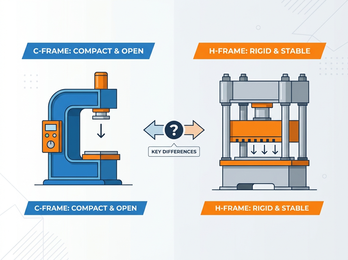
Defining structural integrity requires looking at specific manufacturing tolerances and operational workflows. A press frame must resist massive forces generated during the stamping or forming cycle. If the frame bends, the ram and the bolster plate lose parallelism. This misalignment transfers directly into the workpiece and the tooling. Evaluating frame architecture is the first step in matching a machine to your production requirements.
The C-frame press features an open-gap design resembling the letter "C". This architecture relies on a single massive rear column to support the upper crown and the hydraulic cylinder. The front and sides remain completely open. This open design creates a specific set of physical behaviors under load.
Because the pressing force applies at the front of the "C" while the structural support sits at the back, a moment arm is created. When the hydraulic cylinder extends and meets resistance, the force pushes up on the crown and down on the bed. The rear column acts as a fulcrum. This physics model means the frame must be exceptionally thick at the back to resist bending. Manufacturers often weld heavy steel plates to form a rigid spine.
Despite this structural challenge, the open-gap design offers unmatched operational freedom. Operators gain three-sided access to the working area. This geometry heavily influences material handling strategies on the shop floor.
Operators can easily slide long or awkwardly shaped materials through the side gaps without obstruction.
Scrap removal systems and conveyors can sit directly beside the press bed.
Tooling adjustments require less reaching and bending, improving overall ergonomics for setup technicians.
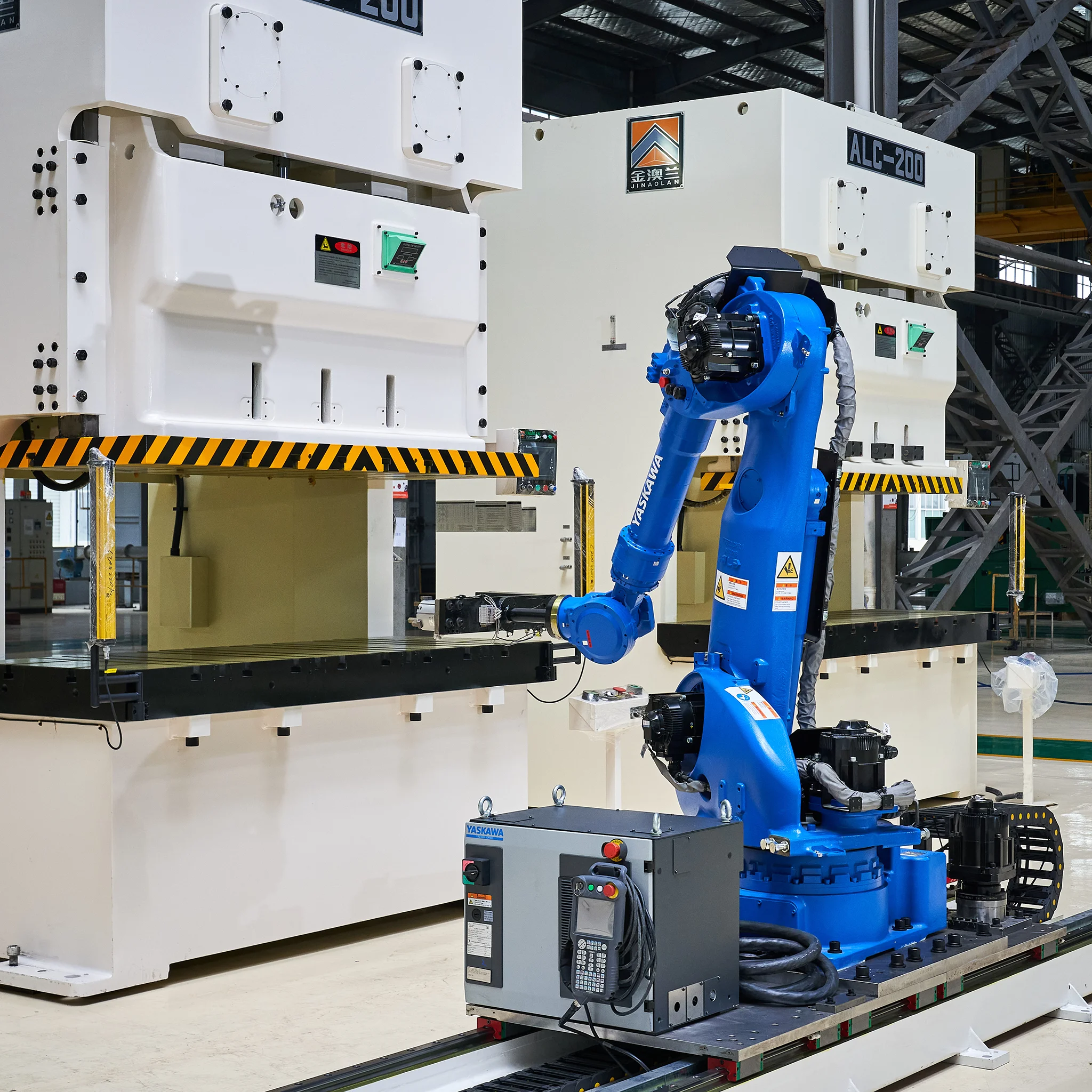
Robotic arms have clear paths to pick and place components during automated cycles.
Maintenance teams can access hydraulic lines and lubrication points without navigating around heavy side pillars.
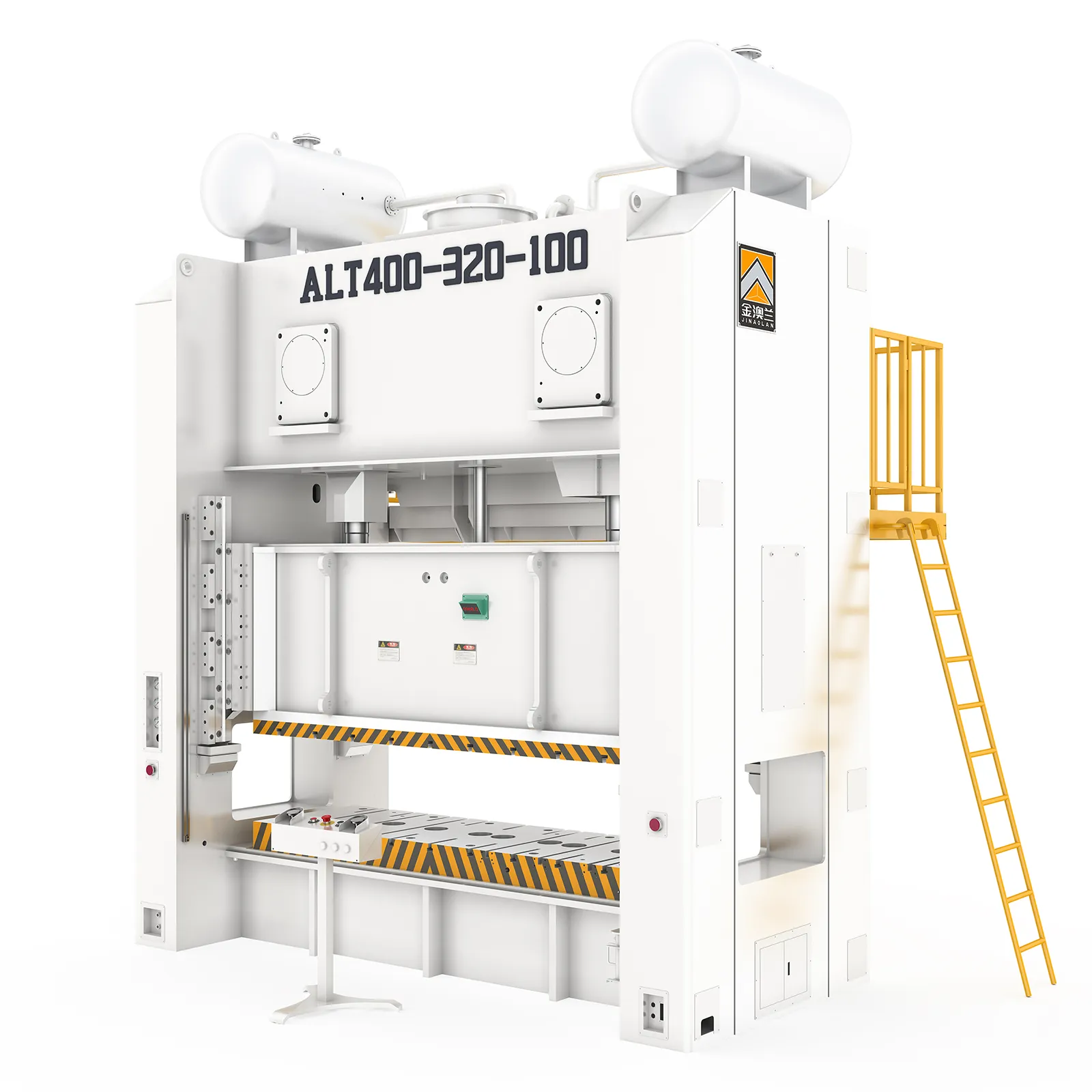
The H-frame press utilizes a closed-frame design. This structure typically consists of either four heavy vertical pillars (tie-rod design) or solid vertical side walls (straight-side design). The crown, bed, and side supports form a complete, unbroken loop resembling an "H" or a solid box.
This closed loop changes the physics of the pressing operation entirely. When the ram presses down, the opposing forces travel straight up the vertical columns. There is no moment arm. The load distributes evenly across the entire platen. The structural loop contains the operational forces completely within the vertical axis. In tie-rod designs, massive steel rods run through the columns. These rods are hydraulically tensioned or shrunk-fit to keep the entire frame in constant compression.
Because the force remains contained vertically, the ram maintains strict parallelism with the bed. The frame does not bend backward. This uniform force distribution allows H-frames to handle massive tonnage without compromising the structural geometry. The trade-off is restricted access. Operators can only load parts from the front or the back, as the side columns block lateral movement.
Comparing frame architectures requires looking at how they perform under stress. Raw tonnage, deflection limits, and cycle speeds dictate which press belongs on your shop floor. You must evaluate how each design handles the specific physical demands of your tooling.
Tonnage dictates the maximum force a press can exert. Due to their physical designs, C-frames and H-frames occupy different tonnage brackets. C-frames generally max out at lower capacities. Most standard C-frames operate between 10 and 250 tons. Pushing a single-column design beyond 250 tons requires an impractically large and heavy rear frame to prevent structural failure. The steel required to prevent bending becomes too massive to manufacture economically.
H-frames easily scale into the thousands of tons. The four-post or straight-side design handles massive force scaling efficiently. You will commonly see H-frames operating at 500, 1000, or even 5000 tons in heavy industrial applications like aerospace forging or automotive panel stamping.
Force distribution also varies wildly. In a C-frame, the force concentrates near the center of the ram but biases slightly toward the rear column under heavy load. Off-center loading on a C-frame exacerbates frame stress. In an H-frame, the force distributes evenly across the entire bed. This even distribution allows H-frames to utilize massive bolster plates for large progressive dies. The pressure remains consistent from the center to the outer edges of the tooling, ensuring uniform part quality.
Angular deflection, commonly called "yawning," is the most critical performance metric when evaluating these presses. Yawning occurs in C-frames when the open front flexes upward under peak load. The "C" literally tries to open up.
When the frame yawns, the ram tilts slightly forward. It loses parallelism with the bolster plate. Even a deflection of a few thousandths of an inch causes severe problems for tight-tolerance tooling. Punches enter the die matrix at an angle. This uneven entry shears the edges of the tooling. Galling occurs on the punch flanks. You will experience premature die wear, increased burrs on stamped parts, and frequent tooling maintenance.
H-frames eliminate yawning. The closed structural loop prevents the crown from flexing upward. The ram remains perfectly parallel to the bed throughout the entire stroke. This zero-deflection characteristic makes H-frames mandatory for high-precision progressive die stamping. If your parts require strict parallelism and microscopic tolerances, the closed frame is the only viable engineering choice.
Hydraulic stroke speeds depend on the pump and cylinder configuration, but frame design influences overall production cycle times. C-frames often facilitate faster overall cycles for smaller parts.
The open design allows operators to load blanks and remove finished parts rapidly. There are no side columns to navigate around. For manual or semi-automated operations, this ergonomic advantage shaves seconds off every cycle. Over a single shift, these saved seconds translate into significantly higher production volumes for small-to-medium components. Light curtains can be mounted easily to protect the open sides without hindering access.
H-frames typically cycle slower in manual operations due to restricted access. Operators must reach straight in and pull straight out. However, when paired with continuous coil feeders and automated progressive dies, H-frames achieve massive production volumes. The press runs continuously while the servo feeder pushes material through the front and out the back. The rigidity of the frame allows for higher stroke rates in automated setups without risking tooling damage.
Press selection goes beyond the workpiece. You must evaluate how the machine interacts with your building, your operators, and your material handling systems. A press that fits your part but breaks your floor is a failed installation.
Floor space is premium real estate in any manufacturing facility. C-frames require significantly less square footage than equivalent-tonnage H-frames. Their compact footprint allows you to tuck them into tight corners or integrate them directly into existing assembly lines.
Portability is a major advantage for gap-frame designs. You can easily move most C-frames with a standard heavy-duty forklift. This mobility supports lean manufacturing principles. If you need to reconfigure a cellular manufacturing layout for a new product run, you simply unplug the C-frame and drive it to the new location. They rarely require permanent mounting or specialized anchors.
High-tonnage H-frames are permanent fixtures. They demand large footprints. They also require significant vertical height clearance for the crown and hydraulic reservoir. Installing a 500-ton H-frame often involves specialized riggers, overhead bridge cranes, and substantial facility modifications. You cannot easily relocate an H-frame once it is installed.
Ergonomics directly impact operator fatigue and safety. The C-frame excels in this category for manual operations. The open sides allow operators to manipulate complex part geometries without straining. If a part requires bending on multiple axes, the operator can rotate the piece freely through the side gaps.
H-frames restrict access. Operators must stand directly in front of the machine. Loading heavy or awkward parts requires reaching deep into the press bed. This restricted front-to-back access dictates strict operator positioning. To mitigate ergonomic strain on H-frames, facilities often must invest in die lifters, conveyors, or robotic loading assists.

Both architectures support automation, but they integrate differently with peripheral equipment.
C-frames pair perfectly with robotic pick-and-place systems. A robotic arm can sit to the side of the press, load a blank, wait for the stroke, and remove the finished part without ever blocking the front operator station. Tooling changeovers are also faster. Technicians can slide dies in and out from three different directions.
H-frames integrate best with heavy-duty coil feeders and scrap choppers. The material feeds linearly through the machine. However, tooling changeovers take longer. Because the side columns block lateral access, technicians must load heavy dies from the front or back. This often requires specialized die carts, heavy-duty forklifts, or overhead cranes to position the tooling safely between the pillars.
Evaluation Metric | C-Frame Press Characteristics | H-Frame Press Characteristics |
|---|---|---|
Structural Design | Open-gap, single rear column support | Closed-loop, 4-post or straight side walls |
Tonnage Range | Light to Medium (10 - 250 tons) | Medium to Heavy (100 - 5000+ tons) |
Deflection Risk | Prone to angular deflection ("yawning") | Zero angular deflection under rated load |
Operator Access | Excellent (Three-sided access) | Restricted (Front and back access only) |
Mobility & Rigging | High (Forklift portable, freestanding) | Low (Requires riggers, permanent installation) |
Tooling Changeover | Rapid (Side loading possible) | Slower (Requires front/rear die carts or cranes) |
Matching the frame to the application prevents premature machine failure and ensures product quality. Different manufacturing processes demand specific structural behaviors. Applying the wrong frame geometry to a demanding process guarantees excessive downtime.
C-frames dominate day-to-day production assembly. They are the workhorses of light manufacturing. Their speed and accessibility make them perfect for operations that require frequent manual intervention.
Riveting and staking operations where operators manually position small assemblies.
Light blanking and punching of thin-gauge sheet metal.
Coining small emblems or tokens where extreme tonnage is not required.
Straightening shafts or bars where the operator needs to visually inspect the part from multiple angles.
Cellular manufacturing setups requiring frequent machine repositioning.
Trimming die-cast components where scrap falls away easily through the open sides.
H-frames handle the heavy lifting. You must specify an H-frame when the process generates massive resistance or requires absolute precision. The rigid structure ensures the tooling survives the process.
Deep drawing of metals, which requires uniform pressure across a large surface area to prevent tearing.
Heavy forming and bending of thick steel plates or structural components.
High-precision progressive die stamping where any angular deflection would destroy the carbide tooling.
Compacting dense powder metals into solid forms.
Processing oversized parts that physically exceed the throat depth of any available C-frame.
Blanking advanced high-strength steels (AHSS) that generate severe reverse snap-through forces.
High-volume manufacturing facilities rarely rely on a single press architecture. Instead, they deploy both types in tandem to optimize workflow and protect their equipment investments. This dual-press strategy routes specific tasks to the most appropriate machine.
The logic is straightforward. You route day-to-day, high-speed assembly and light punching to the C-frames. This keeps production moving quickly and takes advantage of the fast manual loading times. You reserve the H-frames strictly for heavy, precision-critical, or oversized tasks.
By keeping heavy-duty work off the C-frames, you prevent frame fatigue and yawning. By keeping light assembly off the H-frames, you avoid bottlenecking your most powerful machines with simple tasks. This strategic routing maximizes the lifespan of both press types and optimizes overall shop floor throughput. A well-planned facility might feature a central line of heavy H-frames for primary blanking and forming, surrounded by satellite cells of C-frames for secondary assembly and hardware insertion.
Every equipment installation carries inherent risks. Understanding the limitations of your chosen architecture allows you to implement engineering controls before production begins. Proactive planning prevents catastrophic tooling failures and facility damage.
If you must use a C-frame for a process nearing its maximum capacity, you must mitigate the risk of angular deflection. Ignoring yawning will destroy your tooling.
First, specify a heavier-duty frame during the purchasing phase. Look for models with reinforced rear columns and thicker side plates. Second, operate the press well below its maximum rated tonnage. If you need 100 tons of force, buy a 150-ton press. Running at 60% capacity significantly reduces frame flex.
Finally, utilize die sets with heavy-duty guide pins and bushings. The guide pins force the upper and lower die halves to remain aligned, absorbing some of the lateral stress caused by the frame yawning. While this transfers wear to the guide pins instead of the frame, replacing pins is much cheaper than replacing a shattered carbide punch. You can also install deflection monitors that halt the press if yawning exceeds a programmed threshold.
Installing an H-frame requires extensive facility planning. You cannot simply drop it on the floor and plug it in. You must manage the space and access limitations proactively.
Plan your die-handling equipment before the press arrives. Because you cannot load dies from the side, you must ensure you have adequate aisle space in front of the press for die carts or forklifts. If the dies are exceptionally heavy, you may need to install an overhead bridge crane specifically for that press station. Consider adding hydraulic die lifters in the bolster plate to make positioning heavy tooling easier for your setup crews.
Assess your structural foundation requirements immediately. High-tonnage H-frames generate massive dynamic loads. They punch downward with immense force, sending shockwaves into the floor. A standard 6-inch concrete slab will crack under this stress. You often must cut the existing floor, dig a pit, and pour a specialized, steel-reinforced concrete isolation pad. Failing to plan for this foundation work will cause massive installation delays.
The choice between a C frame press vs H frame press ultimately hinges on the strictness of your precision tolerances, the physical dimensions of your parts, and your facility's need for machine mobility. There is no universally superior design. There is only the correct engineering application for your specific workflow.
If your operation prioritizes speed, minimal footprint, portability, and operator accessibility for light-to-medium tasks, you should shortlist C-frames. They offer the flexibility required for agile manufacturing. If your operation demands high tonnage, zero angular deflection, and heavy-duty forming for oversized parts, you must shortlist H-frames. The closed-loop rigidity is non-negotiable for precision work.
To finalize your equipment selection, execute the following steps:
Calculate the exact tonnage required for your toughest application, then add a 20% safety margin to prevent running the machine at maximum capacity.
Review the die wear history on your current machines to identify if angular deflection is already causing hidden maintenance issues.
Measure your available floor space, including the required aisle width for die carts and material handling equipment.
Consult with a structural engineer to verify your concrete floor can handle the dynamic shock loads of a new installation.
For manufacturers evaluating press configurations and complete stamping-line solutions, Zhejiang Jinaolan Machine Tool has specialized in stamping equipment since 1983 and manufactures mechanical presses ranging from 25 to 2,400 tons. Beyond press machines, the company has developed integrated capabilities in progressive die stamping lines, feeding systems, stamping dies, transfer equipment, and intelligent press controls to support more complete production-line requirements.
A: Generally up to 200-250 tons, though custom builds exist. Beyond this, H-frames are structurally necessary for safe and precise operation. Pushing a gap-frame design past this limit requires an impractically large rear column to prevent the frame from bending under extreme pressure.
A: Due to the open front design, high pressure causes the "C" shape to flex open slightly. The rear column acts as a fulcrum. This flexing alters the parallelism between the ram and the bed, causing the upper tooling to tilt slightly out of alignment during the stroke.
A: Both can be automated, but H-frames are typically preferred for continuous coil feeding and progressive dies due to their rigidity. C-frames are excellent for robotic pick-and-place systems because the open sides provide unobstructed access for robotic arms to load and unload parts.
A: High-tonnage H-frames often require reinforced concrete pads or pit foundations to manage weight and operational vibration. The dynamic shockwaves generated during heavy stamping can crack standard factory floors. This is unlike most freestanding, portable C-frames which sit on standard slabs.
A: It is generally not recommended. Deep drawing requires uniform pressure and strict parallelism to prevent material tearing. Any angular deflection will ruin the draw. This makes the rigid, zero-deflection H-frame the industry standard for deep drawing applications.
A: C-frames typically allow for faster tooling changes due to unobstructed side access. Technicians can slide dies in easily. H-frames may require specialized die retrieval systems, die carts, or overhead cranes due to side-column obstructions that force front-or-back-only loading.



