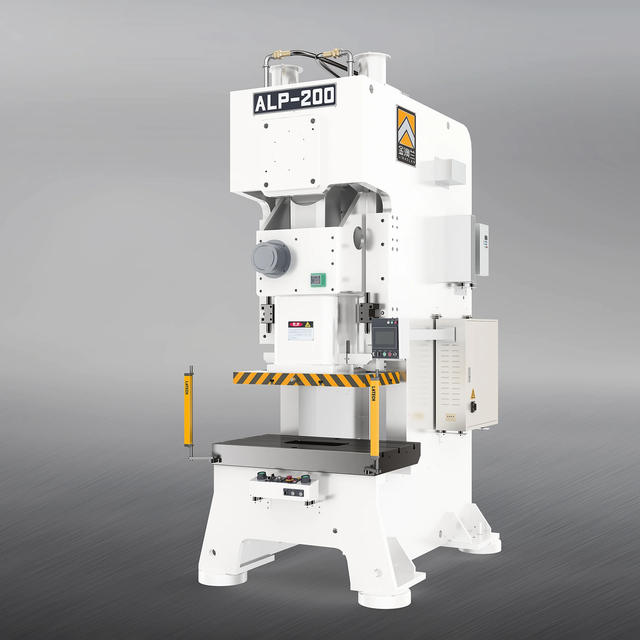
loading


CHARACTERISTICS OF ALP SERIES EQUIPMENT
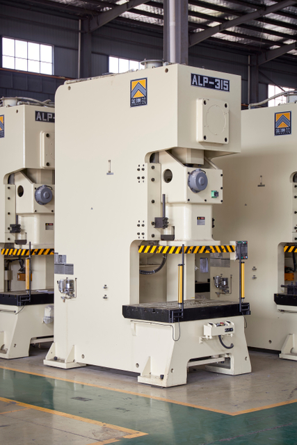
1,Small variation in die height, small dynamic center deviation; The service life of mold has significantly increased; Deformation of stamping is small; Lower cutting noise during blanking.
2,High precision work realization, low noise, and convenient operation.
3,Fixed lock hexagonal guide rail; High rigidity body; Small comprehensive clearance gap.
ALP-110
KINGLAN
| Availability: | |
|---|---|
| Quantity: | |
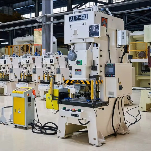
The KINGLAN ALP-110 is designed for the stamping and forming processes used in aluminium foil container production. Working together with dedicated foil container dies and an automatic feeding system, the press converts aluminium foil material into food containers, trays, lids and other thin-wall packaging products through continuous blanking and forming operations.
For manufacturers planning a new foil container production line or expanding existing capacity, the ALP-110 can be configured according to container dimensions, foil specifications, die design and required production output.
The ALP-110 can be used with different dies to manufacture a variety of aluminium foil packaging products, including:
Aluminium foil food containers
Takeaway food trays
Catering containers
Baking trays
Airline meal containers
Disposable aluminium trays
Foil container lids
Other formed aluminium foil packaging
Different container shapes and sizes require corresponding tooling and production settings. The appropriate press and die configuration should therefore be selected according to the actual product design.
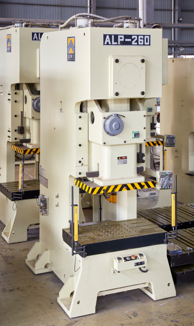
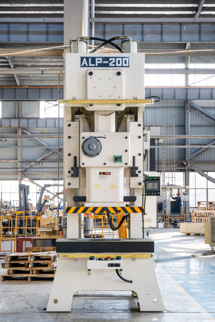
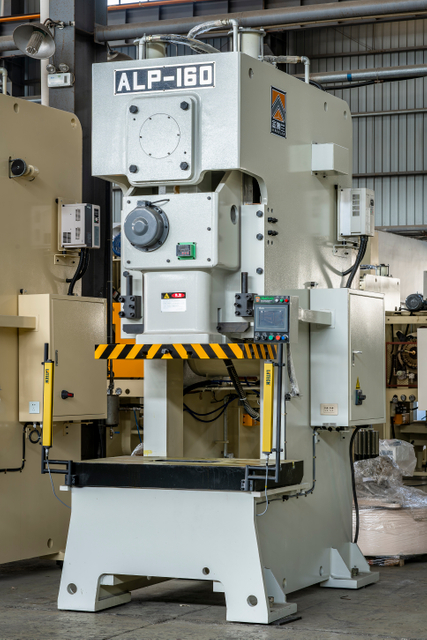
Model | unit | ALP-25 | ALP-35 | ALP-45 | ALP-60 | ALP-80 | ALP-110 | ALP-160 | ALP-200 | ALP-260 | ALP-315 | ||||||||||
Type | Ton | V | H | V | H | V | H | V | H | V | H | V | H | V | H | V | H | V | H | V型 | H型 |
Stroke | mm | 60 | 30 | 70 | 40 | 80 | 50 | 120 | 60 | 150 | 70 | 180 | 80 | 200 | 90 | 200 | 100 | 250 | 150 | 250 | 150 |
Stroke Per Minute | S.P.M | 60-140 | 130-200 | 40-120 | 110-180 | 40-100 | 100-150 | 35-90 | 80-120 | 35-80 | 80-120 | 30-60 | 60-90 | 20-50 | 40-70 | 20-50 | 50-70 | 20-40 | 40-50 | 20-40 | 40-50 |
Tonnage Rated Point | mm | 3.2 | 1.6 | 3.2 | 1.6 | 3.2 | 1.6 | 4 | 2 | 4 | 2 | 6 | 3 | 6 | 3 | 6 | 3 | 7 | 3.5 | 7 | 3.5 |
Die Height(D.H) | mm | 200 | 215 | 220 | 235 | 250 | 265 | 310 | 340 | 340 | 380 | 360 | 410 | 460 | 510 | 460 | 510 | 500 | 550 | 500 | 550 |
Slide Adjustment | mm | 50 | 55 | 60 | 75 | 80 | 80 | 100 | 110 | 120 | 120 | ||||||||||
Slide Area | mm | 470*220*50 | 520*250*50 | 560*300*60 | 700*360*70 | 770*420*70 | 910*470*80 | 990*550*90 | 1130*630*90 | 1130*700*100 | 1200*800*100 | ||||||||||
Bolster Area | mm | 680*300*70 | 800*400*70 | 850*440*80 | 900*500*80 | 1000*550*90 | 1150*600*110 | 1250*800*140 | 1400* | 1500*840*180 | 1700*950*180 | ||||||||||
Dia Of Shank Hole | mm | Φ38 | Φ38 | Φ38 | Φ50 | Φ50 | Φ50 | Φ65 | Φ65 | Φ65 | Φ70 | ||||||||||
Main Motor | KW*P | 2.2*4 | 2.2*4 | 3.7*4 | 5.5*4 | 7.5*4 | 11*4 | 15*4 | 18.5*4 | 22*4 | 30*4 | ||||||||||
Slide Adjust Structure | mm | ManuaI opearation | EIectric driving | ||||||||||||||||||
Required Air Pressure | kgf/cm2 | 5-6 | 5-6 | 5-6 | 5-6 | 5-6 | 5-6 | 5-6 | 5-6 | 5-6 | 5-6 | ||||||||||
Press Accuracy | CNS(JIS)1cIass | ||||||||||||||||||||
Press Dimension(L*W*H) | mm | 1390*920*2125 | 1450*900*2300 | 1650*1040*2390 | 1670*1090*2750 | 1820*1328*3005 | 1970*1458*3218 | 2285*1559*3610 | 2465*1790*4058 | 2585*1945*4433 | 2900*1950*4600 | ||||||||||
Die Cushion(Optional) | — | One Plate One Cylinder | One Plate One Cylinder | One Plate One Cylinder | One Plate One Cylinder | One Plate One Cylinder | One Plate One Cylinder | One Plate One Cylinder | One Plate One Cylinder | One Plate One Cylinder | |||||||||||
Capacity | Ton | — | 2.3 | 2.3 | 3.6 | 3.6 | 6.3 | 10 | 14 | 14 | 14 | ||||||||||
Stroke Length | mm | — | 50 | 50 | 70 | 70 | 80 | 80 | 100 | 100 | 100 | ||||||||||
Cushion Area | mm | — | 300*230 | 300*230 | 350*300 | 450*310 | 500*350 | 650*420 | 710*480 | 810*480 | 810*480 | ||||||||||
Aluminium foil container production combines material feeding, stamping and forming into a continuous manufacturing process.
A typical production flow is:
Aluminium Foil Roll → Material Feeding → Press & Die → Blanking and Forming → Finished Foil Container
The aluminium foil is continuously delivered to the working area by the feeding system. During each press cycle, a dedicated die cuts and forms the material into the required container profile. Different dies can be developed for round, rectangular, compartment and other container designs.
The actual production process may vary according to the container structure, number of die cavities and line configuration.
Selecting a foil container press is not based on press tonnage alone. Container geometry, foil thickness, tooling dimensions and production targets all affect equipment selection.
When evaluating an aluminium foil container project, the following information should be considered:
Container Size and Shape
The dimensions and geometry of the finished container determine the required tooling area and forming process.
Aluminium Foil Specifications
Material grade, width and thickness affect feeding, forming and die requirements.
Die Configuration
Single-cavity and multi-cavity dies may require different working areas and production configurations.
Production Capacity
Target output influences press speed, die configuration, feeding system and overall line design.
Tooling Requirements
The press working area, stroke and die height should match the selected aluminium foil container die.
KINGLAN can evaluate these factors together to recommend a suitable press and production configuration.
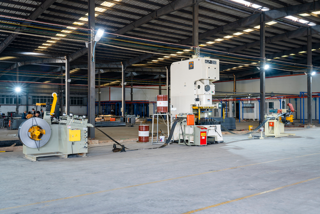
The ALP-110 can operate with dedicated aluminium foil container tooling and material feeding equipment for repeated production cycles.
Its press configuration supports accurate die operation and controlled material forming, while the feeding system continuously positions aluminium foil for each stamping cycle. This makes the machine suitable for manufacturers seeking to automate repetitive foil container production.
For applications with different tooling dimensions or forming requirements, other ALP Series press capacities are also available.
A foil container production project requires more than the press itself. The press, die and material handling equipment need to work together as one production system.
KINGLAN can configure a foil container manufacturing solution with equipment such as:
Provides the stamping motion required for blanking and forming aluminium foil into the required container profile.
The die determines the container’s shape, size, and cavity layout and can be customized to specific product requirements.
Continuously delivers aluminium foil material into the press and coordinates material positioning with the stamping cycle.
Decoiling and related material handling equipment can be incorporated according to the foil roll and production line configuration.
By matching these components to the same production requirement, manufacturers can establish a more integrated aluminium foil container stamping process.
Different foil containers require different manufacturing solutions. Instead of selecting a press based only on a standard machine model, the production system should be evaluated around the finished product.
For a new project, KINGLAN can review:
Container drawings or samples
Container dimensions and shape
Aluminium foil specifications
Required die cavities
Expected production capacity
Available production space
Automation requirements
Based on this information, the press, die and feeding configuration can be evaluated for the specific application.
What machine is used to make aluminium foil food containers?
Aluminium foil containers are typically manufactured using a press equipped with a dedicated container-forming die and material feeding system. The exact equipment configuration depends on the container design, foil specifications and required production capacity.
Can the ALP-110 produce different aluminium foil container shapes?
The press can work with different compatible dies for various container designs. Round, rectangular and other container formats require corresponding tooling designed for the specific product.
Can one press be used with different foil container dies?
Different compatible dies may be used on the same press when the tooling dimensions, required forming force, stroke, die height and other technical requirements are within the machine's operating range. Tooling compatibility should be evaluated before production.
What determines the output of an aluminium foil container production line?
Production output is influenced by several factors, including press speed, number of die cavities, container design, foil feeding system, tooling configuration and overall line setup.
Do I need a feeder for aluminium foil container production?
For continuous production from aluminium foil rolls, an automatic feeding system is generally used to position material accurately for repeated stamping cycles. The feeder specification should match the foil material and press configuration.
How do I choose the right press for my foil container?
Provide the container drawing or sample, foil material specifications, thickness, tooling information and target production capacity. These details can be used to evaluate the required working area, press capacity, stroke and feeding configuration.
STANDARD ACCESSORIES | Electric Grease Lubrication System | ||
Hydraulic overload protection device | S | Pneumatic Die Cusion Device | O |
Manual Grease Lubrication System | S | Quick Die Change Device (Die Lifter,Clamp And Die Arm) | O |
Inverter | S | Slide Knock-out Device | O |
Manual Slide Adjust Device (ALP-60 and below) | S | Anti-vibration pad | O |
Electric Slide Adjust Device (ALP-80 and above) | S | Photoelectric safety device | O |
Mechanical Die Height Indicator (ALP-60 and below) | S | Feeder | O |
Electric Die Height Indicator (ALP-80 and above) | S | Uncoiler | O |
Slide and die balancing device | S | Leveler | O |
Rotary Cam Switch | S | Transfer Arm | O |
Air Source Connector | S | Front Feeding Shaft End (ALP-80 and above) | O |
Overrun protection device | S | Left(Right) Feeding Shaft End | O |
Tool Box | S | ||
Precut Counter | S | ||
Preset Counter | S | ||
Misfeeding Detection Socket | S | ||
Power Supply | S | ||
Front Feeding Shaft End (ALP-60 and below) | S | ||
Die Room Light | S | ||
| Specifications | ALP-25 | ALP-35 | ALP-45 | ALP-60 | ALP-80 | ALP-110 | ALP-160 | ALP-200 | ALP-260 | ALP-315 | ||||||||||
| Model | v | H | v | H | v | H | v | H | v | H | v | H | v | H | v | H | v | H | v | H |
| AA | 840 | 900 | 950 | 1000 | 1170 | 1290 | 1390 | 1680 | 1850 | 1800 | ||||||||||
| AB | 700 | 800 | 790 | 860 | 980 | 1100 | 1200 | 1400 | 1560 | 1600 | ||||||||||
| AC | 368 | 500 | 550 | 600 | 690 | 800 | 870 | 980 | 1050 | 1000 | ||||||||||
| AD | 680 | 800 | 850 | 900 | 1000 | 1150 | 1250 | 1400 | 1500 | 1700 | ||||||||||
| AE | 408 | 488 | 502 | 526 | 544 | 616 | 600 | 800 | 900 | 1000 | ||||||||||
| AF | 470 | 520 | 560 | 700 | 770 | 910 | 990 | 1130 | 1130 | 1200 | ||||||||||
| AG | 540 | 620 | 670 | 720 | 780 | 920 | 990 | 1150 | 1280 | 1390 | ||||||||||
| AH | 920 | 900 | 1040 | 1090 | 1328 | 1458 | 1559 | 1790 | 1945 | 1950 | ||||||||||
| BA | 1150 | 1200 | 1400 | 1420 | 1595 | 1720 | 2070 | 2250 | 2360 | 2690 | ||||||||||
| BB | 910 | 1050 | 1250 | 1220 | 1295 | 1320 | 1770 | 1840 | 2090 | 2330 | ||||||||||
| BC | 1390 | 1450 | 1650 | 1670 | 1820 | 1970 | 2285 | 2465 | 2585 | 2900 | ||||||||||
| HA | 715 | 702 | 702 | 700 | 732 | 711 | 752 | 826 | 802 | 780 | ||||||||||
| HB | 795 | 790 | 790 | 785 | 830 | 830 | 900 | 995 | 1030 | 1000 | ||||||||||
| HC | 200 | 215 | 220 | 235 | 250 | 265 | 310 | 340 | 340 | 380 | 360 | 410 | 460 | 510 | 460 | 510 | 500 | 550 | 500 | 550 |
| HD | 60 | 30 | 70 | 40 | 80 | 50 | 120 | 60 | 150 | 70 | 180 | 80 | 200 | 90 | 200 | 100 | 250 | 150 | 250 | 150 |
| HE | 2125 | 2300 | 2390 | 2750 | 3005 | 3218 | 3610 | 4058 | 4433 | 4600 | ||||||||||
| HF | / | / | / | / | 1505 | 1489 | 1619 | 1650 | 1670 | 1540 | ||||||||||
| ΦH | Φ18 | Φ18 | Φ23 | Φ23 | Φ28 | Φ28 | Φ35 | Φ33 | Φ40 | Φ40 | ||||||||||

content is empty!