
Views: 0 Author: Site Editor Publish Time: 2026-10-12 Origin: Site


Selecting heavy-duty forming equipment dictates production capacity, part quality, and facility layout for decades. Forming a Large Sheet Metal Panel requires balancing immense tonnage requirements against precise deflection control. You must manage material flow and cycle time efficiency simultaneously. Choosing the wrong drive mechanism or frame type leads to high scrap rates, accelerates premature die wear, and causes extensive downtime. This guide provides a technical evaluation framework comparing hydraulic, mechanical, and servo-driven systems. We detail how drive kinematics and frame architecture align with specific large-format stamping requirements. You will learn to match machine specifications directly to your part geometry and production volume. By understanding these mechanical differences, you can specify the exact equipment needed for your production line without over-engineering or under-sizing the installation.
Hydraulic presses deliver full tonnage throughout the entire stroke, making them the default choice for deep drawing large, complex panels.
Mechanical presses (specifically link-drive configurations) offer superior strokes-per-minute (SPM) for high-volume, shallower panel production.
Servo-driven presses provide programmable stroke profiles, combining the deep-draw capabilities of hydraulic systems with the speed of mechanical presses, albeit at a higher initial CapEx.
Straight-side (H-frame) architecture is mandatory for large panel production; gap-frame presses cannot provide the necessary rigidity to prevent angular deflection under off-center loads.
Table of Contents
Calculating the correct tonnage is the first step in specifying a large sheet metal press. Engineers calculate required tonnage based on material shear strength, material thickness, and the total perimeter of the cut or form. The basic blanking formula multiplies the perimeter length by the material thickness and the material's shear strength. You must then add a safety factor, typically 20 percent, to account for tool wear and material variations.
For example, blanking a panel with a 120-inch perimeter from 0.125-inch mild steel (50,000 PSI shear strength) requires 375 tons of force. Adding the 20 percent safety factor pushes the requirement to 450 tons. Different materials drastically alter this calculation.
Material Type | Average Shear Strength (PSI) | Forming Characteristic |
|---|---|---|
Aluminum (5052-H32) | 28,000 | Prone to galling, requires polished tooling |
Mild Steel (1018) | 50,000 | Highly predictable material flow |
Stainless Steel (304) | 75,000 | High work-hardening rate, requires slow draw speeds |
Advanced High-Strength Steel (AHSS) | 120,000+ | Extreme springback, high snap-through shock |
Bed size, or bolster area, is equally critical. The bed must accommodate large progressive dies or transfer die systems completely. Tooling must never overhang the bolster plate. Overhanging dies create severe tipping moments during the stamping cycle. This uneven loading damages the slide guides and causes premature die failure. When sizing the bed, account for the physical footprint of the die shoes, clamping mechanisms, and any in-die sensing equipment. You also need clearance for automated scrap removal systems beneath the bed.
Different stamping operations require specific press force, speed, and motion control. Blanking and punching demand high-speed operation and shock resistance, while deep drawing requires controlled forming speed and sustained force. Bending and coining depend on precise force delivery near bottom-dead-center (BDC). Matching press capabilities to the operation improves forming accuracy, reduces die wear, and ensures consistent production quality.
Draw depth and material flow directly influence stamping quality. Press stroke length, available tonnage, and ram speed must match the panel geometry and material properties. Proper blank-holder pressure, controlled through die cushions or nitrogen springs, helps prevent wrinkling and tearing during deep drawing. Accurate force and motion control support consistent panel dimensions.
Strokes per minute (SPM) determine stamping productivity, but higher speeds do not always improve efficiency. Blanking operations can generally run faster, while deep drawing requires slower, controlled movement to prevent material damage. Optimizing stroke length, forming speed, and automated feeding helps balance production output, part quality, and equipment efficiency.
Hydraulic presses provide controllable forming force throughout the stroke, making them suitable for deep drawing and large-panel forming. Adjustable ram speed, stroke length, and dwell time help manage material flow and reduce defects. Although generally slower than mechanical presses, hydraulic systems offer flexibility for automotive panels, appliance housings, and complex metal components.
Mechanical presses use flywheel-driven mechanisms to deliver high-speed, repeatable stamping operations. Standard crank presses suit blanking and shallow forming, link-drive presses provide slower forming motion for improved material flow, and knuckle-joint presses deliver high force near BDC for coining and precision sizing. Their high productivity makes them suitable for continuous manufacturing.
Servo-driven presses use programmable motor control to adjust ram speed, position, and motion profiles throughout the stroke. They support operations such as deep drawing, blanking, and precision forming while improving process flexibility and potentially reducing energy consumption. Although initial investment and control-system complexity are higher, servo presses offer advantages for manufacturers producing varied panel designs.
Drive Type | Tonnage Availability | Speed (SPM) | Best Application | Primary Limitation |
|---|---|---|---|---|
Hydraulic | Full stroke | Slow to Medium | Deep drawing, variable stroke | Fluid maintenance, slower cycles |
Mechanical (Crank) | Near BDC only | Very High | Blanking, shallow forming | Fixed stroke, high impact shock |
Mechanical (Link) | Near BDC only | High | Moderate drawing, auto panels | Complex mechanical linkage |
Servo-Driven | Programmable | Medium to High | Complex forming, multi-purpose | High initial capital expenditure |
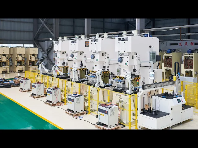
Straight-side (H-frame) presses provide high structural rigidity and uniform load distribution, making them ideal for large-panel stamping. Their reinforced frames, preloaded tie-rods, and precision slide guides minimize deflection and maintain slide-to-bolster parallelism. This stability improves forming accuracy, reduces die wear, and supports consistent production under high-tonnage loads.
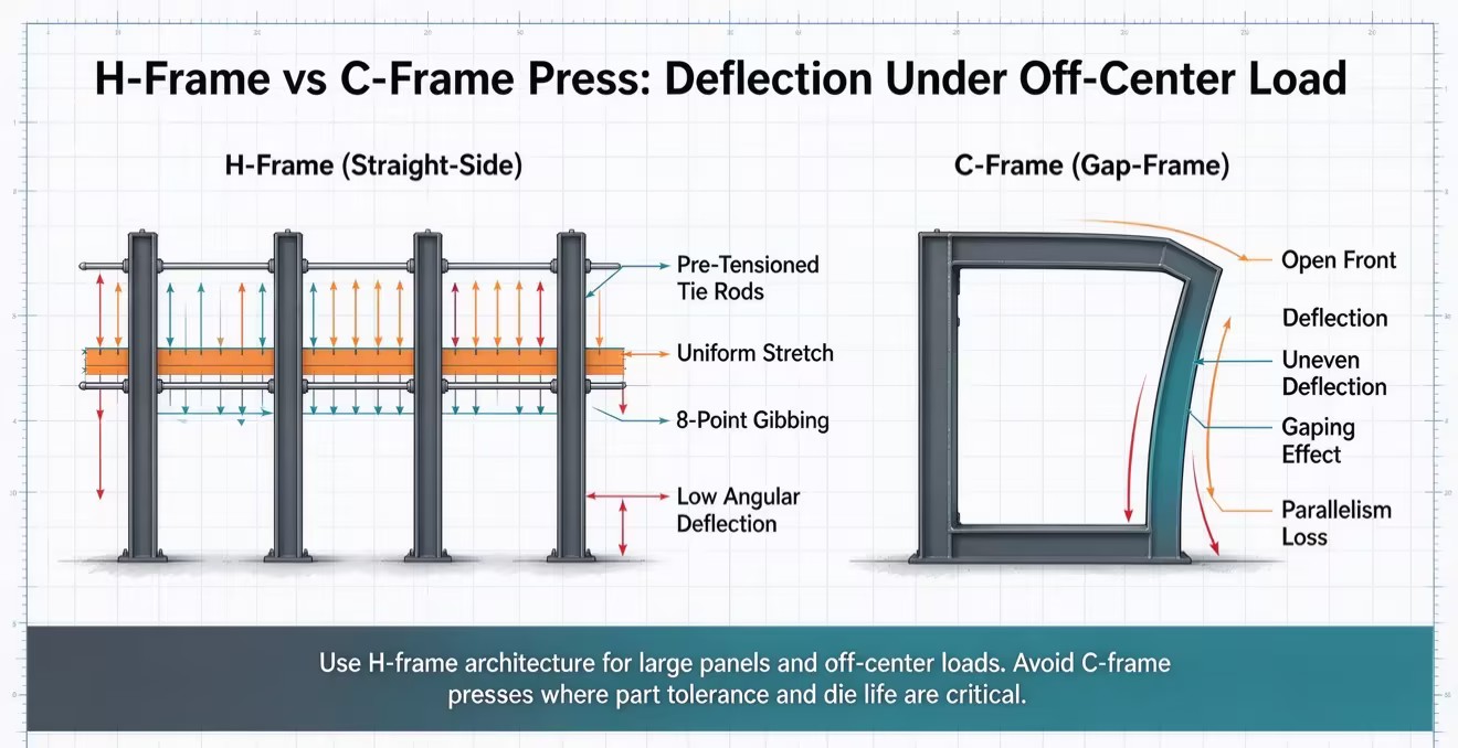
Gap-frame (C-frame) presses offer convenient tooling access and flexible material handling but are more susceptible to frame deflection under heavy or off-center loads. Excessive deformation can affect die alignment, accelerate tooling wear, and reduce part accuracy. For large-panel stamping, straight-side presses are generally preferred when high rigidity and precision are required.
Tooling compatibility directly affects stamping quality and production flexibility. Die cushions control blank-holding force during deep drawing, helping prevent wrinkles and material tearing. Hydraulic cushions provide adjustable pressure control, while Quick Die Change (QDC) systems simplify tooling replacement and reduce downtime. Selecting compatible tooling and automation features improves efficiency and forming consistency.
Automated material handling improves safety, efficiency, and consistency in large-panel stamping. Destackers, robotic transfers, and double-blank detectors support reliable sheet feeding and part movement. Proper synchronization between the press and transfer equipment prevents collisions, protects tooling, and enables stable high-volume production.
Press energy efficiency depends on drive technology, operating cycles, and production requirements. Hydraulic presses offer flexible force control, mechanical presses are efficient for continuous high-volume stamping, and servo presses provide programmable motion with potential regenerative energy recovery. Evaluating electricity consumption, maintenance costs, and production efficiency helps manufacturers optimize long-term operating expenses.
Calculate exact tonnage requirements using material shear strength and perimeter formulas, adding a 20 percent safety margin to account for tool wear.
Audit your facility's foundation capacity, pit depth potential, and overhead crane limits before finalizing any equipment specifications.
Request physical die trials from shortlisted manufacturers using your actual tooling and production material to verify material flow dynamics.
Specify straight-side frame architectures exclusively to prevent angular deflection and protect your tooling investments from off-center loading damage.
A: Tonnage depends entirely on material thickness, shear strength, and total cut perimeter. While there is no universal minimum, forming large automotive or appliance panels typically requires machines starting at 600 tons. Heavy-duty applications frequently exceed 2,000 tons to handle the necessary blanking forces and provide adequate bed space for large transfer dies.
A: Hydraulic systems are superior for deep drawing. They deliver full rated tonnage throughout the entire stroke length. This allows for deep, controlled material flow without stalling the motor. Mechanical systems lose available tonnage higher up in the stroke, making deep draws difficult or impossible without severely oversizing the machine.
A: Yes, in many applications. Servo drives offer programmable stroke profiles, allowing them to mimic the slow forming speeds and dwell times of hydraulic systems. They provide the deep-draw capabilities of hydraulics combined with the high-speed retract and approach phases of mechanical systems, offering unmatched flexibility on the shop floor.
A: A die cushion applies upward pressure against the blank holder ring inside the die. This controlled holding pressure prevents the sheet metal from wrinkling as it is pulled into the die cavity during deep draw operations. It manages material flow and maintains part integrity across complex geometries.
A: Off-center loading occurs when forming forces are not perfectly centered under the ram, creating severe tipping moments. You must select a straight-side (H-frame) design with robust 8-point slide guides to resist these forces. Gap-frame machines deflect unevenly under off-center loads, destroying part tolerances and accelerating die wear.
A: High-tonnage machines require deep concrete pits to house lower frame components, die cushions, and scrap conveyors. The foundation must feature heavily reinforced concrete designed to absorb dynamic shock loads. Soil bearing tests, sump pumps for fluid management, and vibration isolation pads are mandatory engineering requirements prior to installation.



