
Views: 0 Author: Site Editor Publish Time: 2026-08-10 Origin: Site


In metal stamping and forming operations, precision relies on the exact dimensional alignment between the press machinery and the tooling. Miscalculating or improperly setting the shut height is a primary cause of catastrophic die crashes, premature tool wear, and severe damage to press components such as the pitman arm or crankshaft. For technical buyers and engineering supervisors, failing to match press specifications with existing die inventories leads to unusable equipment or costly retrofitting. This guide breaks down the technical mechanics of power press shut height, how it dictates die compatibility, and the critical evaluation criteria required when standardizing setup procedures or procuring new press machinery.
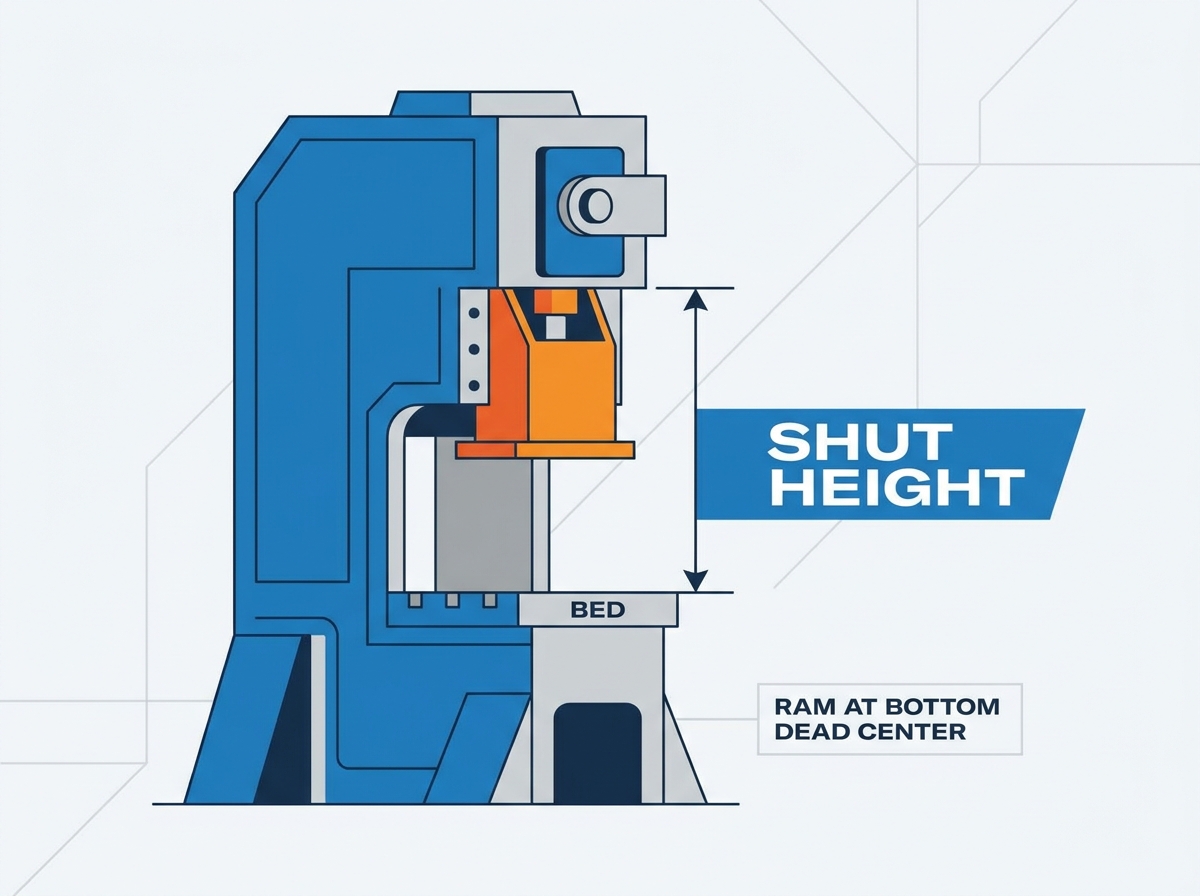
Technical Baseline: Power press shut height is strictly defined as the distance from the bottom of the slide (ram) to the top of the press bed (lower worktable) when the stroke is at Bottom Dead Center (BDC) and the slide adjustment is at its highest point.
Die Height Distinction: Press shut height is a fixed machine dimension (with an adjustment range), whereas die height (closed height) is a tooling dimension. The available press space must always accommodate the die height plus any bolster plates.
Risk Mitigation: Standardizing shut height calculations and die setter training prevents over-adjustment, which can compromise the press's tonnage capacity and structural integrity.
Procurement Impact: When evaluating a new power press, the slide adjustment range and shut height specifications must align with the facility's largest and smallest dies to ensure operational flexibility without requiring excessive shimming or riser plates.
Table of Contents
Understanding machine dimensions requires strict adherence to standardized measurement points. You measure shut height from the bottom face of the ram, also known as the slide, directly down to the top surface of the press bed. The press bed serves as the primary lower worktable where the bolster plate typically mounts. To establish an accurate baseline measurement, the machine must be in a specific mechanical state. The press stroke must be positioned exactly at Bottom Dead Center (BDC). Furthermore, the slide adjustment mechanism must be positioned all the way up. This configuration represents the maximum possible vertical distance between the slide and the bed at the bottom of the stroke.
When measuring this distance, operators must ensure both surfaces are completely free of debris, heavy oil, or metal slugs. Even a small piece of scrap metal trapped under a measuring tool will throw off the baseline calculation. You must measure from the actual machined face of the slide, not from any attached sub-plates or quick-die-change (QDC) hardware, unless those components are permanently affixed and factored into the machine's permanent specifications.

You must distinguish between machine dimensions and tooling dimensions. Die height, frequently called closed height, represents the overall vertical height of the die set when it is fully closed. In this state, the upper punches are fully engaged within the lower die block, and the guide pins are seated to their maximum working depth. Press shut height is a fixed machine parameter that features a specific adjustment range. The relationship between these two metrics dictates operational compatibility.
The press's working shut height must always equal the die height plus the thickness of any bolster plate used in the setup. If the die rests directly on a bolster, that plate thickness consumes part of the available machine space. Tooling engineers design dies to operate at a specific closed height to ensure the material forms correctly without over-compressing the nitrogen gas springs or urethane strippers built into the tool.
Metric |
Category |
Definition |
Measurement State |
|---|---|---|---|
Press Shut Height |
Machine Dimension |
Distance from slide face to press bed. |
Stroke at BDC, slide adjustment fully up. |
Die Height (Closed Height) |
Tooling Dimension |
Total vertical height of the closed die set. |
Punches fully engaged in the die block. |
Open Height |
Machine Dimension |
Distance from slide face to press bed. |
Stroke at TDC, slide adjustment fully up. |
Slide Adjustment Range |
Machine Capability |
Total vertical travel of the pitman screw. |
Measured from maximum up to maximum down position. |
Shop floor communication often suffers from terminology overlap. Many machinists and tooling suppliers interchangeably use the terms "die height" and "shut height." They frequently combine them into the colloquial phrase "die shut height." This habit creates significant confusion during equipment specification. Technical buyers and engineers must enforce strict definitions between machine dimensions and tooling dimensions. Allowing these terms to blur leads to costly procurement errors.
For example, a tooling supplier might state a die requires a "24-inch shut height." If the buyer assumes this means the press needs a 24-inch shut height, they might order a machine that is too small once the 6-inch bolster plate is installed. The buyer should have specified a press with a 30-inch shut height to accommodate the 24-inch die plus the 6-inch bolster. Clear terminology prevents these expensive miscalculations.
Bolster plates provide a standardized mounting surface for tooling, but they directly reduce the effective shut height of the press. When you attach a bolster plate to the press bed, you permanently occupy a portion of the vertical clearance. You must account for this reduction during every setup. Engineers use a standard formula to determine the actual working envelope.
The formula is straightforward: Available Die Space = Power Press Shut Height - Bolster Plate Thickness. Failing to subtract the bolster thickness guarantees a miscalculation, often resulting in severe tooling damage during the initial stroke. If a facility uses multiple bolster plates of varying thicknesses for different operations, die setters must physically verify the installed plate before adjusting the slide.
Insufficient shut height clearance inevitably leads to a die crash. When operators set the slide too low, the press attempts to drive the upper die shoe past the physical limits of the lower die shoe. The mechanical force of the press overwhelms the tooling structure. This collision shatters brittle carbide tooling components instantly. It also cracks heavy steel die shoes, bends precision guide pins, and destroys internal cam mechanisms.
The financial impact of a die crash extends far beyond routine maintenance. Replacing shattered carbide punches or repairing cracked die shoes costs thousands of dollars. It also halts production lines, causing missed delivery deadlines and severe operational downtime. In extreme cases, a severe die crash can permanently warp the press ram, requiring a complete machine teardown and slide remachining.
A mechanical press does not deliver its maximum rated tonnage throughout the entire stroke. It delivers maximum force at a very specific distance above Bottom Dead Center, typically rated at 1/4-inch or 1/2-inch above BDC depending on the machine's design. Improper slide adjustment alters this critical dynamic. When operators adjust the slide incorrectly to compensate for a mismatched shut height, they change where the tool contacts the material relative to the stroke cycle.
If the die engages the material too high in the stroke, the press lacks the mechanical advantage to complete the work. This leads to press stalling, where the machine locks on bottom. Freeing a locked press requires specialized hydraulic release mechanisms or dangerous manual intervention. Furthermore, hitting the material too high on the tonnage curve causes severe overload, which can fracture the press frame or snap the pitman arm.
Slide Position Error |
Mechanical Consequence |
Operational Impact |
|---|---|---|
Slide set too low (Over-compression) |
Die blocks collide; tonnage spikes instantly. |
Shattered tooling, cracked die shoes, press frame stress. |
Slide set too high (Under-compression) |
Punches fail to penetrate material fully. |
Incomplete parts, heavy burrs, failure to eject scrap. |
Die engages material too early in stroke |
Press operates outside its rated tonnage curve. |
Motor stalling, clutch slipping, locked on bottom. |
Standardizing shut heights across a press fleet drastically reduces die setting time. Single-Minute Exchange of Die (SMED) methodologies rely on predictable, repeatable setups. When every press features a known, documented working space, operators spend less time jogging the slide and measuring clearances. Facilities often use standardized parallels or sub-plates to normalize die heights across their entire inventory.
By making all dies effectively the same height, you minimize the need for major slide adjustments during changeovers. This approach transforms a tedious, error-prone setup process into a rapid, efficient operation. Instead of cranking the slide motor for five minutes to bridge a 10-inch gap between different dies, the operator only needs to make minor micro-adjustments to account for material thickness variations.
Human error remains the leading cause of setup failures. Formal training programs for engineers, supervisors, and die setters are mandatory for safe operations. Personnel must thoroughly understand shut height mechanics to prevent catastrophic manual setup errors. Training establishes accountability on the shop floor. When die setters understand the physics behind the slide adjustment mechanism, they respect the physical limits of the machinery.
Standardized training ensures that every operator follows the exact same verification procedures before engaging the clutch. This includes reading the setup sheet, verifying the bolster thickness, checking the shut height indicator, and performing a manual bar-over or slow jog to confirm clearance before switching to continuous run mode.
Safety protocols must precede any physical measurement or adjustment. You must implement strict lockout/tagout (LOTO) procedures before placing hands inside the die space. Isolate the main power and bleed all residual pneumatic pressure from the clutch and counterbalance systems. Insert physical safety blocks between the ram and the bed to prevent gravity from pulling the slide down unexpectedly.
Once the machine is safe, verify the physical components in the work envelope. Measure the exact thickness of the bolster plate currently installed using precision calipers. Confirm the dimensions of any required parallels or riser blocks. Never assume these components match the setup sheet without physical verification. A previous shift might have swapped a 4-inch bolster for a 6-inch bolster without updating the documentation.
Setting the slide requires a methodical approach to ensure precision and prevent equipment damage. Follow these core steps during every setup:
Verify the die is properly located and clamped to the bolster plate.
Remove the safety blocks and restore power to the slide adjustment motor.
Bring the press stroke to exact Bottom Dead Center (BDC) using the machine's inching or jog mode. Watch the crank angle indicator to ensure it reads exactly 180 degrees.
Adjust the slide downward slowly until the upper die shoe makes contact with the lower die shoe or designated setup blocks.
Apply the required setup pressure to ensure all components are seated properly against the bolster. Do not over-compress.
Lock the pitman and slide adjustment mechanism securely to prevent any vertical drift during high-speed operation.
Perform a single test stroke without material to verify smooth operation and proper clearance.
Facilities frequently encounter dies that are too short for a press's minimum shut height. You cannot simply extend the slide adjustment past its engineered limits to reach a short die. Doing so exposes too much thread on the pitman screw, creating a massive structural weakness. Instead, you must bridge the gap safely.
The proper protocol involves utilizing engineered riser blocks, precision parallels, or thicker bolster plates. These components safely elevate the tooling to meet the slide. Never use random scrap metal, unground plates, or stacked washers to bridge this gap. Uncalibrated shims compress unevenly under tonnage, causing the die to shift, the punches to shear, and the press ram to experience severe off-center loading.
Even experienced die setters make critical measurement errors during setup. Failing to account for material thickness in the die closed height calculation is a frequent mistake. The die must accommodate the sheet metal; ignoring this causes over-compression. If you are stamping 0.125-inch steel, the slide must be set to accommodate that extra material volume.
Another common error involves relying on worn or uncalibrated shut height indicators. Mechanical counters and digital readouts drift over time due to heavy vibration. Finally, operators often ignore the compression forces of nitrogen gas springs or urethane strippers. These components exert massive upward pressure. If you do not account for this resistance, the slide adjustment will be inaccurate under actual working loads, leading to dimensional variations in the stamped parts.
Procuring a new press requires a comprehensive audit of your current die inventory. You must measure the closed heights of your largest and smallest active dies. This data determines the required maximum and minimum shut height for the new machine. You must also evaluate the stroke length in conjunction with this dimension. Adequate clearance is mandatory for part ejection and automated material handling.
Transfer systems and servo feeders require specific open heights at Top Dead Center (TDC). If the shut height accommodates the die, but the stroke is too short, your automation systems will crash into the tooling. When reviewing press specifications, map out the entire stroke cycle to ensure the transfer fingers have enough time and vertical space to enter the die, grab the part, and exit before the ram descends.
Buyers must choose between motorized and manual slide adjustment systems. Motorized adjustments, equipped with digital encoders, carry a higher upfront cost. However, they provide significant long-term labor savings in high-mix, low-volume stamping environments. Operators can input a specific dimension into the control panel, and the slide automatically moves to the correct position, eliminating manual cranking.
Manual systems require physical labor and take longer to set, making them better suited for dedicated presses that run the same die for months at a time. You must also evaluate the locking mechanisms. Hydraulic locking systems offer superior holding force and resist vibration better than traditional mechanical locks, reducing maintenance requirements and preventing slide drift over the life of the press.
A press's tonnage rating is not a flat line; it is a curve. You must review the manufacturer's tonnage curve chart before finalizing a purchase. The press must deliver the required force at the specific shut height where the die begins working the material. This is especially critical when comparing deep drawing operations to standard blanking.
Blanking requires high tonnage very close to BDC, where the press naturally has the most mechanical advantage. Deep drawing requires sustained tonnage higher up in the stroke, where the mechanical advantage is weaker. If the press cannot deliver the necessary force at the precise moment of material contact, the equipment will stall or suffer structural failure. Always overlay your die's force requirements onto the press's tonnage curve chart.
Extending the slide adjustment too far introduces severe mechanical risks. When you adjust the slide beyond its intended range, you expose too much thread on the pitman screw. This drastically reduces the structural rigidity of the connection between the slide and the crankshaft. Operating the press in this condition risks catastrophic thread shear under heavy tonnage loads.
If the pitman threads strip, the slide will collapse onto the die, destroying the tooling and potentially fracturing the press frame. You must strictly adhere to the manufacturer's maximum adjustment limits. Many modern presses include electronic limit switches to prevent over-adjustment, but older mechanical presses rely entirely on the operator's discipline and visual inspection of the screw threads.
A die might fit perfectly within the shut height parameters at BDC but still fail operationally. This occurs when there is insufficient open clearance at Top Dead Center (TDC). Servo feeders, robotic transfer fingers, and scrap removal conveyors require physical space to operate between stroke cycles.
If the press stroke is too short relative to the required shut height, the automation equipment will not have time or space to clear the die area. This results in smashed feeder components and jammed material strips. When calculating clearances, always factor in the lift height of the stripper plate and the ejection trajectory of the finished part.
Strict documentation is the most effective mitigation strategy against setup errors. Implement standardized setup sheets that detail the exact shut height indicator reading for every specific die in your inventory. Operators should never guess or rely on memory. The setup sheet must also list the required bolster thickness and any necessary parallels.
Additionally, use physical setup blocks, often called stop blocks, mounted directly inside the die. These blocks provide a hard physical limit. If an operator adjusts the slide too low, the press hits the stop blocks before over-compressing the delicate punches and die cavities. Stop blocks act as a final mechanical failsafe against human error.
Shut height indicators are precision instruments that require routine maintenance. Establish a strict preventative maintenance schedule to calibrate these devices. Maintenance personnel must physically verify that the digital readout or mechanical counter perfectly matches the true slide-to-bed measurement.
Use certified precision blocks and dial indicators to confirm accuracy. Place the precision blocks on the bed, lower the slide until it touches, and compare the physical block height to the indicator reading. If an indicator drifts by even a few thousandths of an inch, it can cause accelerated tool wear or poor part quality. Routine calibration ensures that your operators can trust the numbers on the control panel.
Conduct a comprehensive physical audit of all active die heights in your facility to establish a baseline for future equipment purchases.
Verify the accuracy of existing press shut height indicators using certified calibration blocks and dial indicators.
Implement standardized setup sheets that explicitly list the required slide position and bolster thickness for every tool in your inventory.
Consult with press manufacturers to align future equipment purchases with your standardized tooling requirements, ensuring adequate slide adjustment ranges.
Founded in 1983, Zhejiang Jinaolan Machine Tool manufactures mechanical presses and integrated stamping-line equipment, including feeding systems, stamping dies, and transfer solutions. Its 25- to 2,400-ton press range supports manufacturers seeking equipment matched to tooling dimensions, automation requirements, and production capacity.
A: Shut height is the distance from the slide to the bed at Bottom Dead Center with the adjustment up. Open height is the distance at Top Dead Center with the adjustment up, dictating the maximum clearance for part removal.
A: Bring the ram to Bottom Dead Center, move the slide adjustment to its highest position, and measure the vertical distance from the bottom face of the ram to the top of the press bed or lower worktable.
A: The press shut height is a fixed machine dimension, but the bolster plate reduces the available die space. Available space equals press shut height minus bolster thickness.
A: Setting it too low causes the press to attempt to close past the physical limits of the die, resulting in a die crash, shattered tooling, or a stalled press locked on bottom.
A: A mechanical counter or digital readout on the press that displays the current position of the slide adjustment, allowing operators to return to precise settings for specific dies.
A: You cannot change the maximum shut height designed into the machine's frame, but you can alter the working shut height within a specific range using the slide adjustment mechanism.
A: It is a common industry colloquialism to refer to the closed height of a die as its "shut height." However, technically, shut height refers to the press machine's dimension, while closed height refers to the tooling.



