
Views: 0 Author: Site Editor Publish Time: 2026-09-21 Origin: Site


Mechanical power press reliability hinges on a single, fundamental mechanism. The stopping mechanism dictates operator safety and determines maximum production throughput. Failing or legacy stopping systems introduce severe operational risks to any stamping floor. Inconsistent stopping times compromise safety barriers, rendering light curtains ineffective. Scrap rates climb when the ram fails to engage precisely at the programmed crank angle. OSHA and ANSI compliance violations become a looming threat when stopping times drift beyond acceptable limits. Unplanned downtime from a shattered clutch plate or burnt brake lining halts entire stamping lines, disrupting downstream assembly processes.
Plant managers and maintenance engineers require a structured, engineering-based approach to evaluate these mechanisms. This technical guide explores how to assess, compare, and select the right upgrades. We examine tonnage, flywheel inertia, thermal capacity, and production requirements to ensure optimal performance. Engineering teams can specify systems that eliminate erratic ram behavior and restore absolute control over the press stroke.
Safety and Compliance First: Modernizing a press clutch and brake directly impacts OSHA compliance and ANSI B11.1 safety distance calculations by ensuring repeatable, reliable stopping times.
Wet vs. Dry System Trade-offs: Dry systems offer lower upfront costs and simpler maintenance, while wet systems provide superior heat dissipation, noise reduction, and longevity for high-cycle applications.
Control Integration is Critical: Upgrading mechanical components must be paired with modern, redundant press control systems—including cross-monitored dual safety valves—to realize full safety and performance benefits.
Table of Contents
A power press clutch and brake system controls the transfer and stopping of flywheel energy.
The clutch transfers energy from the flywheel to the crankshaft to drive the ram. The brake stops the ram accurately when required. Both systems must work together to ensure smooth operation and safe stopping.
Important performance factors include:
Engagement Speed: Determines how quickly the press responds after activation.
Torque Capacity: Ensures the clutch transfers enough power without slipping.
Stopping Time: Maintains consistent stopping performance and supports safety requirements.
A reliable system should provide stable stopping times under different operating conditions.
Early detection helps prevent downtime and equipment damage. Common warning signs include:
Slow Engagement: May indicate air leaks, worn seals, or control valve issues.
Abnormal Noise: Often caused by worn friction plates or mechanical parts.
Longer Stopping Distance: Indicates brake wear or reduced braking performance.
Frequent Control Errors: May result from pressure problems or control system faults.
Friction Dust or Metal Particles: Shows excessive wear inside the clutch or brake system.
Regular inspection helps maintain press accuracy, safety, and production efficiency.
Different clutch and brake designs suit different production requirements. The main choices include dry systems, wet systems, and separate or combination configurations.
Dry systems use compressed air to engage friction plates. The friction surfaces are exposed to air, making inspection and maintenance easier.
Advantages:
Simple structure
Easy maintenance
Suitable for low and medium production requirements
Limitations:
Heat can build up during high-speed operation
More friction dust is generated
Stopping performance may decrease under heavy cycling conditions
Dry systems are commonly used for standard production lines and press retrofit projects.

Wet systems place friction plates inside an oil-filled housing. The oil helps remove heat and improves performance during continuous high-speed operation.
Advantages:
Better heat control
Longer service life
Suitable for high-cycle and heavy-duty stamping
Limitations:
More complex installation
Requires oil maintenance and cooling systems
Wet systems are preferred for demanding applications where stable performance is required over long production periods.
Combination Units
Clutch and brake components are integrated into one assembly. This design provides easier installation and improves safety by preventing clutch and brake overlap.
Separate Units
Clutch and brake components are installed separately. This configuration offers more flexibility for special press designs and high-torque applications.
Type | Main Advantage | Suitable Application |
|---|---|---|
Dry System | Simple maintenance | Standard stamping |
Wet System | Better heat control | High-speed production |
Combination Unit | Compact and safe | General press systems |
Separate Unit | Flexible configuration | Custom applications |
Choosing the correct clutch and brake system depends on press speed, production requirements, maintenance needs, and operating conditions.
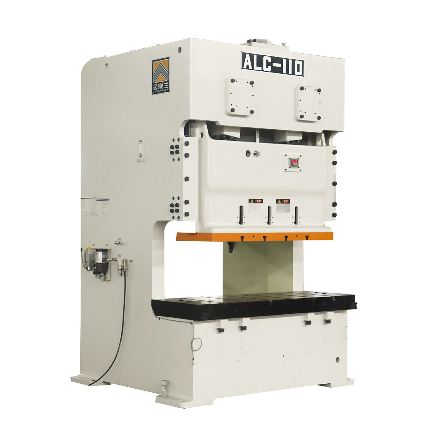
Selecting a power press clutch and brake system requires evaluating safety, production speed, heat management, and torque requirements. A properly matched system improves press reliability and reduces maintenance costs.
Stopping performance directly affects operator safety. The brake must stop the ram within the required time to maintain safe operating conditions.
A brake monitoring system continuously checks stopping performance. If stopping time becomes too long due to wear or reduced brake efficiency, the system can alert maintenance teams before safety risks occur.
Key factors include:
Consistent stopping time
Reliable brake response
Proper safety distance
Regular performance monitoring
High-speed stamping generates significant heat during repeated clutch and brake cycles. If the system cannot remove heat effectively, friction performance may decrease.
Dry systems rely on air cooling and are suitable for standard applications.
Wet systems use oil cooling to control heat and maintain stable performance during high-cycle production.
Choosing the right cooling method depends on press speed, production volume, and operating conditions.
The clutch and brake must match the press capacity and flywheel energy.
Important factors include:
Press tonnage
Flywheel size
Stamping process
Production speed
Heavy-duty forming operations require higher torque capacity than light stamping applications. An undersized system may cause excessive wear, unstable stopping, and reduced equipment life.
The working environment also affects clutch and brake selection.
Dry systems may generate friction dust and higher operating noise. Wet systems provide better dust control because wear particles remain inside the oil system.
For modern production facilities, enclosed systems can help improve:
Workplace cleanliness
Noise control
Maintenance efficiency
Selecting the right clutch and brake system ensures safer operation, stable production, and longer press service life.
Feature / Metric | Dry Friction Systems | Wet Enclosed Systems |
|---|---|---|
Cooling Method | Ambient Air | Circulating Oil Bath |
Best Application | Low/Medium continuous stroking | High-speed, heavy single-stroking |
Maintenance Focus | Air gap adjustment, lining replacement | Oil analysis, filter changes |
Noise Level | High (mechanical clank, air exhaust) | Low (muffled by enclosed housing) |
Particulate Generation | Airborne friction dust | Contained within oil filters |
Heat Fade Resistance | Moderate (drops under heavy load) | Excellent (stable under heavy load) |
Evaluating the long-term operational viability of Clutch and Brake Systems requires a deep understanding of maintenance intervals. Dry configurations demand frequent physical interventions. Maintenance technicians must regularly measure the air gap between the friction plates. As the linings wear, this gap increases, requiring manual adjustment of the shim plates to restore optimal engagement speed. Eventually, the friction linings wear down to the rivets, necessitating a complete teardown and replacement of the friction discs.
Wet configurations drastically alter the maintenance timeline. Because the oil film absorbs the engagement friction, the internal plates experience negligible physical wear. It is common for a wet unit to operate for a decade without requiring internal plate replacement. However, this mechanical longevity shifts the maintenance burden to fluid management. Technicians must perform regular oil sampling to check for viscosity breakdown and particulate contamination. Changing the specialized hydraulic fluid and replacing high-micron filters becomes the primary preventative maintenance task.
Actuation methods directly impact plant energy loads. Pneumatic systems rely on compressed air, which is notoriously inefficient to generate. Every stroke consumes a specific volume of compressed air. Furthermore, aging pneumatic lines often develop micro-leaks, and pressure drops across the plant can cause sluggish clutch engagement. Facilities must ensure their compressor capacity can handle the continuous cubic feet per minute (CFM) demands of large pneumatic clutches.
Hydraulic actuation, often used in heavy-duty wet systems, requires dedicated hydraulic power units (HPUs). These units utilize electric motors to maintain constant fluid pressure. While hydraulic systems provide immense, instantaneous force without the compressibility issues of air, they introduce continuous electrical consumption. Engineers must evaluate the footprint of the HPU, the routing of high-pressure hydraulic lines, and the electrical load of the continuous-duty pump motors when specifying these systems.
Symptom | Probable Cause | Corrective Action |
|---|---|---|
Sluggish Ram Start | Low air pressure or restricted airline | Check compressor output and inspect dual valve for blockages. |
Ram Drifts Past TDC | Worn brake linings or glazed friction plates | Measure air gap. Replace linings if worn beyond OEM limits. |
Excessive Heat Build-up | Clutch/Brake overlap or insufficient cooling | Verify control timing. Check oil flow and heat exchanger in wet systems. |
Loud Clanking on Engagement | Worn drive pins or loose mounting bolts | Inspect mechanical linkages. Torque all mounting hardware to spec. |
Selecting the appropriate stopping mechanism requires a rigorous engineering evaluation of the press's duty cycle and kinetic energy demands. Dry systems provide reliable, easily maintainable solutions for standard continuous operations. Wet systems deliver the extreme heat dissipation and longevity required for high-volume, high-cycle, or environmentally sensitive stamping demands. Upgrading a press clutch and brake restores precise ram control, ensures regulatory compliance, and protects the facility's operators and tooling.
Conduct a comprehensive press audit using calibrated stop-time measurement devices to establish current performance baselines.
Calculate the required safety distance based on current stopping times and ANSI B11.1 standards to identify immediate compliance gaps.
Consult a certified mechanical press engineer to evaluate flywheel inertia and thermal load requirements for your specific stamping applications.
Review modern OEM specifications to ensure retrofit compatibility with existing crankshaft dimensions and available plant air or electrical capacities.
Upgrade legacy relay-logic controls to modern safety PLCs equipped with cross-monitored dual safety valves during the mechanical retrofit.
A: Lifespan depends entirely on the technology and application. Dry friction linings typically last 1 to 3 years depending on cycle rates and thermal loads. Wet systems, because the friction plates are protected by an oil film, often operate for over 10 years before requiring internal rebuilds, provided the oil and filters are maintained strictly.
A: Technicians use a portable or integrated stop-time measurement device. This device triggers the brake at the worst-case stroke position, which is usually 90 degrees on the downstroke. It then measures the exact milliseconds it takes for the ram to come to a complete and total stop.
A: A dual safety valve provides redundant control of the air or hydraulic fluid actuating the stopping mechanism. If one internal valve spool sticks or fails, the secondary spool safely exhausts the fluid or air. This fail-safe action engages the brake and prevents an accidental, uncommanded press stroke.
A: Dry systems use exposed friction plates cooled by ambient air, making them simpler but prone to heat fade and dust generation. Wet systems enclose the friction plates in a circulating oil bath, providing superior heat dissipation, zero airborne dust, and significantly longer mechanical lifespans under heavy single-stroking conditions.
A: Yes. Most legacy mechanical presses can be retrofitted. However, this often requires machining the existing crankshaft to accept new mounting hubs. Furthermore, the mechanical retrofit must be paired with modern press controls and dual safety valves to meet current safety standards.



