
Views: 0 Author: Site Editor Publish Time: 2026-08-24 Origin: Site


High-volume press lines rely on stamping automation to hit aggressive cycle times, maximize output, and keep operators out of the danger zone. The main engineering bottleneck is selecting the right transfer mechanism. If you choose an overly complex system, you inflate capital expenditure and programming time. If you pick an overly simplistic system, you risk die clearance collisions and limit the types of parts you can run in the future. We will evaluate the mechanical differences between these systems based on kinematics, part geometry, precision, and press layout. This technical evaluation framework will help you definitively compare a 2D vs 3D stamping manipulator so you can align mechanical capabilities with your facility's operational goals.
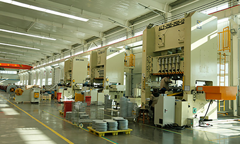
Kinematic Constraints: 2D manipulators operate strictly on planar (X-Y) axes, making them highly efficient for flat part transfers, whereas 3D manipulators add a Z-axis (and often rotational capabilities) necessary for deep-drawn or complex geometries.
Throughput vs. Flexibility: 2D systems generally offer faster cycle times and higher baseline rigidity due to reduced motion paths, while 3D systems sacrifice marginal speed for the flexibility to clear complex dies and reorient parts between presses.
Cost Realities: The upfront cost of a 2D manipulator is significantly lower, making it a budget-friendly option for simple tasks, but long-term calculations must factor in the potential cost of restricted future bidding capabilities if complex part contracts cannot be fulfilled.
Integration Requirements: 3D stamping automation manipulators require more advanced collision avoidance programming, sophisticated end-of-arm tooling (EOAT), and stricter press synchronization compared to 2D variants.
Table of Contents
A 2D stamping manipulator operates on a strictly planar motion profile. The mechanical architecture restricts movement to two primary directions. It utilizes horizontal transfer along the X-axis to move parts between stations. It employs horizontal reach or pitch along the Y-axis to enter and exit the press area. This system lacks independent vertical lifting capabilities. It relies entirely on the press stroke and internal die lifters to elevate the part above the die shoe.
The mechanical simplicity of a 2D system provides massive structural rigidity. Fewer moving axes mean fewer articulation points that can flex under load. This rigidity minimizes vibration during high-speed transfers. Reduced vibration allows for aggressive acceleration and deceleration profiles. You achieve maximum throughput without compromising positional repeatability. The servo motors can drive the linear rails at maximum velocity because they do not have to fight the cantilevered weight of a vertical mast.
These systems excel in specific manufacturing environments. Typical applications include shallow forming operations and flat blank feeding. They dominate progressive die setups where vertical clearance is minimal and parts stay relatively flat. Facilities producing simple brackets, washers, or flat panels benefit immensely from this architecture. The 2D setup provides unmatched reliability for straightforward geometries that do not require complex mid-air manipulation.
A 3D stamping manipulator introduces spatial movement into the press line. The mechanical architecture integrates a dedicated Z-axis for vertical lift. This operates alongside the standard X and Y axes. Many configurations function as advanced 3-axis motion platforms mounted to the press uprights. Others utilize fully articulated robotic arms with six degrees of freedom mounted to the floor. This spatial freedom fundamentally changes how parts move through the press window.
The primary operational advantage is vertical extraction capability. The manipulator can lift parts directly out of deep die cavities. It can tilt, rotate, or flip materials mid-air. This occurs without any direct physical contact by human operators. You can reorient complex geometries between press operations seamlessly. This eliminates the need for intermediate staging tables, turnover stations, or manual intervention between tandem presses.
These systems handle the heavy lifting for complex manufacturing processes. Typical applications include synchronized tandem press lines and deep-draw stamping. Automotive body panels heavily rely on 3D manipulation to clear large scrap chutes and guide pins. Any production run requiring intermediate orientation changes demands this technology. The 3D architecture provides the flexibility needed to run complex part designs that would otherwise crash a planar transfer system.
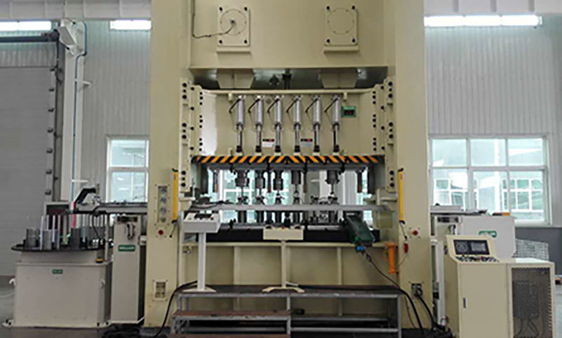
Part geometry serves as the primary filtering criteria for automation selection. Flat parts transfer easily along a horizontal plane. Complex parts present immediate physical obstacles. Deep-drawn components necessitate a 3D manipulator's Z-axis. You must physically extract the part from the lower die cavity. Horizontal transfer cannot begin until the part clears the die boundary and any protruding guide pins.
A 2D system requires specialized tooling to handle complex parts. It relies heavily on pneumatic or nitrogen gas in-die lifters. These lifters push the part up to the transfer height. Engineering complex dies with integrated lifters requires significant capital and maintenance overhead. You must evaluate the cost of engineering these complex dies for every new part. Often, investing in a 3D manipulator proves more efficient than modifying every single die shoe in your inventory.
Die clearance also dictates the required motion path. Guide pins, scrap chutes, and cam units create collision hazards inside the press window. A 2D manipulator must navigate these obstacles linearly, which is sometimes impossible. A 3D system can simply lift the part over the obstructions. This vertical clearance drastically simplifies die design. It reduces the engineering hours required for new tooling development and prevents catastrophic crashes.
Cycle time directly dictates press line profitability. You must compare the acceleration profiles of both systems. 2D manipulators boast superior acceleration and deceleration rates. The simplified mechanics allow for aggressive servo motor tuning. The mass of the moving components is significantly lower. This results in blazing fast point-to-point transfer speeds that keep up with high-speed mechanical presses.
Implementing 3D motion introduces a distinct cycle time penalty. Moving in three dimensions inherently takes longer than a linear path. The Z-axis travel adds critical fractions of a second to each stroke. The manipulator must lift, transfer, and then lower the part. This sequential movement extends the overall transfer window and often requires the press to run at a lower continuous speed.
You must calculate the strokes per minute (SPM) impact carefully when evaluating these systems. Follow these steps to determine the cycle time penalty:
Measure the baseline press stroke time from top dead center to bottom dead center.
Calculate the Z-axis extraction time required to clear the lower die shoe.
Add the X-axis horizontal transfer time between the press stations.
Factor in the Z-axis insertion time required to place the part into the next progression.
Compare the total automated transfer time against the continuous press cycle to find your maximum SPM.
Positioning accuracy relies on minimizing stacked mechanical tolerances. Every moving axis introduces a potential point of variance. 2D manipulators inherently offer higher baseline repeatability. They possess fewer moving parts and fewer articulation points. The rigid linear guides maintain strict alignment during high-speed transfers. This ensures the part lands exactly on the die locators every single time.
A 3D system faces greater engineering challenges to maintain precision. Operating at full extension amplifies minor vibrations. The Z-axis mechanism introduces a cantilever effect during horizontal transfer. This requires heavier structural components to counteract multi-axis vibration. The gantry or base must absorb significant dynamic forces to keep the end-of-arm tooling stable.
Servo motor resolution plays a critical role in 3D accuracy. Advanced absolute encoders must track position across three spatial dimensions simultaneously. The controller must compensate for the momentum of the tooling as it swings through the air. Maintaining tight tolerances requires continuous calibration. You must ensure the 3D system possesses adequate rigidity for your specific payload to prevent part misloads.
The physical layout of your facility dictates equipment selection. The distance between presses in a tandem line is critical. This spacing determines the required manipulator reach. Long transfer distances demand robust mechanical support. A 2D system can span moderate distances using heavy-duty linear rails. However, excessive distance amplifies vibration and deflection on the transfer bar.
Footprint requirements differ significantly between the two architectures. 3D manipulators often require more robust mounting structures. They must handle the complex moment of inertia generated by multi-axis movements. Floor-mounted articulated robots require substantial concrete anchoring and safety fencing. Gantry-style 3D systems need heavy steel superstructures bolted directly to the press crown.
You must evaluate the available space between press uprights. 2D systems generally feature a lower profile. They fit easily into tight press windows and under low ceilings. 3D systems require more vertical clearance above the die. The Z-axis mast or robotic arm needs room to articulate without hitting the press ram. Ensure your press dimensions can accommodate the required spatial envelope before installation.
Tooling weight directly impacts manipulator performance and speed. The payload includes both the stamped part and the EOAT. 2D manipulators can often handle heavier payloads at higher speeds. Their simpler structural dynamics distribute weight more efficiently. The linear guides support the load directly against gravity. This allows the servo motors to focus entirely on horizontal acceleration rather than fighting vertical drop.
3D manipulation requires highly complex end-of-arm tooling. You often need vacuum grippers with compliance mechanisms. These mechanisms absorb slight misalignments during vertical extraction. The EOAT must secure the part during multi-axis rotation. This adds significant weight to the end of the manipulator arm, utilizing heavy aluminum extrusions and multiple pneumatic valve banks.
The Z-axis motor must lift this combined payload against gravity. This limits the maximum acceleration rate of the 3D system. Heavy payloads cause structural deflection at maximum reach. You must carefully calculate the dynamic payload capacity. Ensure the chosen system can handle your heaviest part and tooling combination without sacrificing accuracy or triggering servo overload faults.
Automated transfer systems fundamentally transform workplace safety. Both architectures remove operators from the primary danger zone. Human hands no longer enter the press during the stamping cycle. This effectively eliminates the risk of amputation or crush injuries. Automation ensures compliance with stringent industrial safety regulations and OSHA standards.
3D manipulators provide specific ergonomic advantages for complex production. They eliminate the need for manual mid-process reorientation. Operators no longer need to flip heavy blanks between presses. Handling sharp-edged materials manually causes severe lacerations and strain. The 3D system manages all spatial manipulation autonomously, keeping workers away from sharp sheet metal.
This drastically reduces ergonomic strain and workplace injuries. Repetitive motion injuries plummet when automation handles the heavy lifting. The facility experiences fewer worker compensation claims. Safety protocols shift from physical guarding to electronic interlocks and light curtains. Operators transition to safer roles managing the automation interface from a control pedestal.
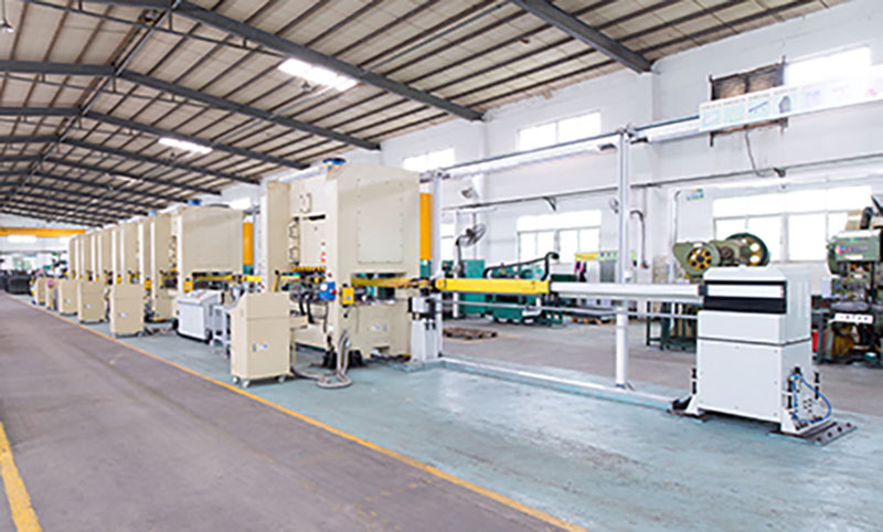
Baseline hardware requirements dictate the initial capital outlay. A 2D system requires fewer servomotors and simpler drive mechanisms. The structural components are less complex to manufacture and assemble. This makes the 2D architecture inherently more budget-friendly for simple tasks. Facilities can automate multiple presses with a lower initial investment, achieving a faster payback period on flat-part production lines.
A 3D system demands a significantly higher capital expenditure. The addition of the Z-axis requires extra motors, precision gearboxes, and heavy-duty ball screws. You must account for the hidden costs of software licensing. Advanced controllers are required to manage 3-axis motion platforms and calculate complex kinematics. These proprietary control systems add substantial upfront expenses to the project.
You must also factor in the cost of specialized EOAT. 3D grippers require complex pneumatic routing, vacuum venturis, and sensor integration. The mounting structures for 3D systems require heavier steel fabrication. Thoroughly evaluate your capital availability before committing to a spatial manipulator. Ensure the production volume and part complexity justify the higher initial investment.
Automated manipulators generate return on investment through increased production speed. A machine operates continuously without fatigue, breaks, or shift changes. The consistent cycle time yields predictable and higher output rates. This increased throughput directly offsets the initial capital expenses. You produce more parts per shift with fewer defects and less scrap.
Automation allows for strategic labor reallocation. You no longer need operators performing manual transfer tasks or loading heavy blanks. These workers transition to higher-value supervisory roles. They manage quality control, perform visual inspections, and handle system optimization. This maximizes the value of your human workforce and improves overall plant morale.
The reduction in scrap material also improves financial returns. Automated transfers prevent part dropping and misalignment damage. The precision handling ensures higher first-pass yield rates. You maximize raw material utilization and reduce waste disposal costs. The overall efficiency of the press line improves dramatically when human error is removed from the transfer process.
Commissioning a 2D system requires fewer engineering hours. The programming relies on simple point-to-point logic. The controller only manages two axes of motion. Integrating the manipulator with the press PLC is straightforward. The handshaking signals consist of basic open/close, top dead center verification, and clear-to-run commands.
A 3D system requires extensive programming and integration effort. Engineers must develop complex path planning algorithms. They must define strict collision zones within the die space to prevent the tooling from crashing into the guide pins. The system requires continuous press-following synchronization. The manipulator must adjust its speed dynamically based on the press ram position to optimize cycle times.
Controller compatibility becomes a major integration hurdle. You must evaluate the ease of integrating proprietary software ecosystems. Open-architecture platforms communicate better with existing legacy PLCs. Proprietary systems often require expensive gateway modules and specialized programmers. Factor these integration hours into your project timeline and resource planning to avoid startup delays.
Mechanical wear profiles differ based on system complexity. 3D systems possess more moving parts and articulation joints. They utilize more servomotors, gearboxes, and bearings. The complex cable management systems flex continuously during spatial movement. These factors inherently increase the number of potential failure points and require a more robust spare parts inventory.
A 2D system offers a simpler maintenance profile. The linear guides require basic lubrication and periodic inspection. The drive belts or rack-and-pinion systems are easily accessible for tensioning. Troubleshooting a two-axis system takes significantly less time. This translates to higher overall equipment effectiveness (OEE) and less unplanned downtime.
You must implement rigorous preventative maintenance schedules for both architectures. 3D systems require specialized technicians for calibration and repair. Spare parts inventory must include specialized absolute encoders and multi-axis servo drives. Plan for slightly higher ongoing maintenance resources when deploying 3D automation to keep the system running at peak performance.
Technical Comparison of 2D and 3D Stamping Manipulators | ||
Engineering Parameter | 2D Manipulator | 3D Manipulator |
|---|---|---|
Kinematic Motion Axes | X, Y (Planar) | X, Y, Z (Spatial) |
Cycle Time Impact | Extremely Fast (High SPM) | Moderate (Z-axis penalty) |
Part Geometry Suitability | Flat, Shallow Forms | Deep-drawn, Complex Shapes |
Die Engineering Requirements | Requires in-die lifters | Standard dies acceptable |
Programming Complexity | Simple point-to-point logic | Complex path planning & collision zones |
Payload Capacity | High (Direct load support) | Moderate (Cantilever limitations) |
Maintenance Overhead | Low complexity | High complexity |
Many facilities fall into the trap of over-specifying equipment. They purchase a 3D manipulator solely for perceived future-proofing. However, they only run flat parts for the foreseeable future. This results in wasted capital expenditure. The facility gains no operational advantage from the unused Z-axis, yet they paid a premium for the capability.
This over-specification also creates unnecessary maintenance overhead. You maintain complex servomotors and software that provide no daily value. The heavier 3D system may actually slow down your flat part production. The cycle time penalty reduces your overall output capacity, meaning you paid more money to produce fewer parts per hour.
Mitigate this risk through rigorous part-mix analysis. Conduct a thorough historical review of your production runs. Forecast future contracts based on realistic market data. Only invest in 3D automation if complex geometries represent a significant portion of your volume. Align the technology directly with your actual production needs rather than hypothetical future scenarios.
Under-specifying automation creates immediate production bottlenecks. A facility deploys a 2D manipulator to save capital. They soon discover it cannot clear the guide pins of a new die. The manipulator cannot navigate around the scrap chutes. This leads to catastrophic collisions, severe tooling damage, and weeks of unplanned downtime.
The 2D system becomes a permanent limitation on the press line. The facility must decline lucrative contracts for deep-drawn parts. They must spend excessive capital engineering complex dies with internal nitrogen lifters to compensate for the manipulator's lack of vertical reach. The initial savings quickly evaporate due to these operational limitations.
Mitigate this risk during the vendor evaluation phase. Mandate comprehensive 3D kinematic simulations before procurement. Require the vendor to perform detailed reach studies using your actual die CAD files. Ensure the proposed 2D system can physically navigate your most complex tooling setups safely without requiring massive die modifications.
Integrating modern automation with older mechanical presses presents unique challenges. Legacy presses often lack precise stopping capabilities. Their clutch and brake systems degrade over decades of use. They lack modern PLC interfaces for seamless communication. This makes synchronization with a high-speed manipulator extremely difficult and dangerous.
A modern 3D stamping automation manipulator requires precise ram position data. It needs to know exactly where the press stroke is at all times. Older presses cannot provide this continuous feedback. This creates severe collision risks if the press drifts past top dead center while the manipulator is inside the die space.
Mitigate this risk by assessing press control upgrades first. You may need to install modern rotary cam limit switches or absolute resolvers. Upgrading the clutch/brake controls with dual safety valves ensures repeatable stopping distances. Modernizing the press PLC is often a prerequisite for successful manipulator installation. Do not connect advanced robotics to outdated press controls.
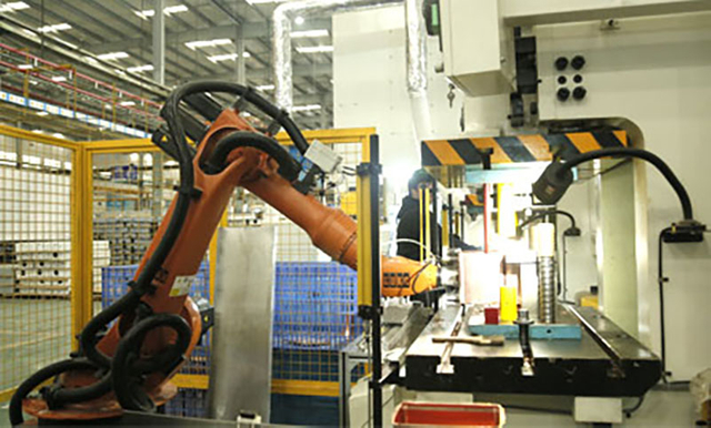
Choosing a 2D system requires specific operational conditions. You must evaluate your current and future production requirements carefully. This architecture excels in high-speed, low-complexity environments. Consider a 2D manipulator when your facility meets the following criteria.
Your production consists entirely of flat blanks or shallow-formed parts.
Your existing dies already incorporate reliable pneumatic or hydraulic lifters.
Maximum strokes per minute (SPM) is the primary driver of profitability.
Capital expenditure budgets are strictly limited for the current fiscal year.
Your maintenance team lacks experience with complex multi-axis servo systems.
The press window offers limited vertical clearance for overhead automation.
Part orientation remains identical throughout the entire progressive stamping process.
A 3D system provides the flexibility needed for modern manufacturing challenges. It handles complex geometries that linear systems cannot process. You must justify the higher investment through increased capability. Consider a 3D manipulator when your facility faces these production realities.
You manufacture deep-drawn components requiring significant vertical extraction clearance.
Parts require mid-air rotation or flipping between tandem press operations.
You want to simplify future die designs by eliminating internal mechanical lifters.
Your facility processes heavy, awkward panels that cause ergonomic injuries manually.
You are bidding on complex automotive or aerospace contracts requiring spatial manipulation.
The press line layout requires navigating over large scrap chutes or bolster extensions.
You require advanced collision avoidance capabilities for highly complex tooling setups.
Selecting the optimal automation architecture defines your production efficiency. You must balance kinematic capabilities against your specific part geometries. A thorough technical evaluation prevents costly implementation errors. Use this knowledge to drive your press line modernization strategy. Follow these actionable steps to begin your automation upgrade.
With experience in press machinery and stamping automation solutions, Kinglan supports manufacturers seeking to improve production efficiency, automation capability, and press line performance. Its industry-focused solutions provide a practical foundation for manufacturers planning new stamping lines or upgrading existing production systems.
Audit your current and forecasted part mix to determine exact vertical lift requirements.
Request 3D kinematic reach studies from vendors using your most complex die CAD files.
Evaluate your legacy press controls to identify necessary PLC or resolver upgrades.
Calculate the cycle time impact of Z-axis movement on your required output rates.
Assess your maintenance team's capability to support multi-axis servo technology.
A: A 2D manipulator cannot lift parts vertically. It only handles deep-drawn parts if the die contains mechanical or pneumatic lifters. These lifters must push the part completely out of the cavity to the transfer height before horizontal movement begins. This requires specialized die engineering.
A: Moving in three dimensions inherently takes longer than moving in two. The vertical Z-axis travel adds fractions of a second to the transfer time. However, optimized path planning and continuous press synchronization can minimize this cycle time penalty significantly.
A: 3D systems require rigorous preventative maintenance. Technicians must inspect multi-axis servomotors, precision gearboxes, and complex cable management tracks. Regular calibration is necessary to maintain spatial accuracy. You must ensure your maintenance staff is trained on advanced motion controllers.
A: Older presses require a control system audit. The press must have reliable stopping capabilities and modern clutch/brake controls. It needs a modern PLC interface and rotary resolvers to communicate precise ram position data to the manipulator's controller.
A: Yes, 2D manipulators are generally more rigid. They have fewer moving axes and articulation joints. This mechanical simplicity minimizes vibration during high-speed transfers. The rigid linear guides maintain strict alignment, offering higher baseline positional repeatability.
A: Yes, many 3D manipulators feature rotational capabilities on the end-of-arm tooling. They can lift a part, rotate or flip it mid-air, and place it into the next press at a completely different orientation. This eliminates the need for manual staging tables.



