
Views: 0 Author: Site Editor Publish Time: 2026-08-24 Origin: Site


Tooling selection dictates the ceiling for production throughput, per-part cost, dimensional consistency, and speed to market. A misalignment between part design and die architecture creates massive operational risks on the shop floor. Over-engineering traps capital in unnecessary tooling that will never see the volume required for a return on investment. Under-engineering destroys margins through high manual labor requirements, slow cycle times, and inconsistent part quality. You must carefully evaluate the primary types of stamping dies—single-stage, compound, combination, and progressive—based on production volume, geometric complexity, and tolerance requirements. This guide breaks down how to match your part geometry to the right tooling strategy, ensuring you deploy capital efficiently while meeting strict engineering tolerances.
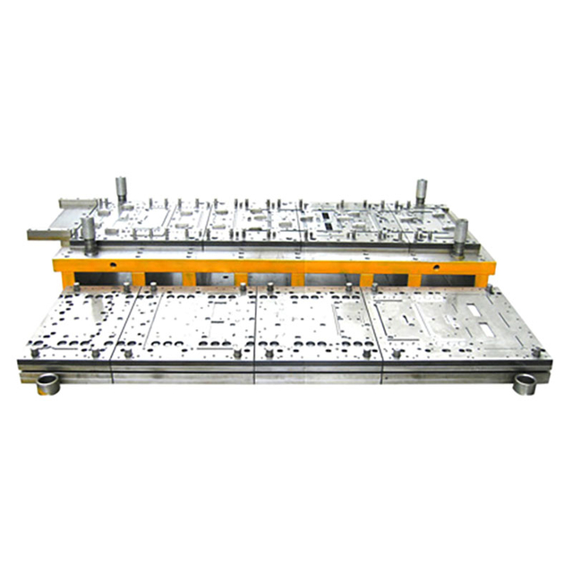
Single-Stage Dies: Best suited for low-volume production, prototyping, or exceptionally large parts where minimizing upfront tooling cost is the primary objective.
Compound Dies: The optimal choice for flat, high-precision parts (like washers or gear blanks) requiring strict concentricity, executing multiple cuts in a single stroke without bending operations. They offer faster build times and lower costs than progressive dies.
Combination Dies: A hybrid approach that performs both cutting and forming (such as bending or embossing) in a single stroke, ideal for specific geometries that require more than a compound die but less than a progressive setup.
Progressive Dies: The standard for high-volume, complex manufacturing, offering the lowest per-part cost at the expense of significant upfront engineering and tooling investment.
Table of Contents
Selecting the correct tooling architecture requires a deep understanding of how sheet metal behaves under pressure. Each die type manages material flow, scrap removal, and part transfer differently. We must establish clear, technical definitions for the core tooling architectures available in metal stamping before matching them to specific production runs.
Single-stage dies perform exactly one operation per press stroke. You design these dies to execute a solitary function, such as blanking a profile, piercing a hole, or bending a flange. Because the die only handles one step, manufacturing a multi-feature part requires a series of distinct single-stage dies lined up across multiple presses.
Operators or robotic arms must manually transfer the workpiece between these discrete presses to complete the part. This transfer requirement significantly limits strokes per minute (SPM). Single-stage tooling requires minimal engineering time and utilizes standard die sets, making it highly accessible for short runs. However, the reliance on external transfer mechanisms increases the risk of positioning errors. If an operator loads a blank slightly off-center in a secondary piercing die, the resulting hole location will fail inspection.
Compound dies represent an advanced form of single-stage tooling. They perform multiple cutting or piercing operations in a single stroke at a single station. Engineers achieve this by nesting the male and female die components together. This nesting allows the tool to cut internal features and the external perimeter simultaneously as the ram hits bottom dead center.
During the press cycle, the material remains securely clamped between the punch and the die face by a heavy spring-loaded stripper plate. This clamping action prevents the metal from distorting or shifting while the cutting edges shear the material. While compound dies primarily focus on cutting, you can sometimes integrate minor surface operations like shallow embossing. They excel at producing perfectly flat parts with flawless concentricity because the internal and external cuts happen at the exact same moment.
Combination dies perform both cutting and forming operations in a single press stroke. Unlike compound dies, which restrict themselves to flat shearing, combination dies introduce 3D forming capabilities at a single station. A common example involves blanking a circular disc and immediately drawing it into a shallow cup before the press returns to top dead center.
Timing is the most difficult engineering challenge within a combination die. The tool must complete the cutting action just before the forming action begins. This sequence allows the material to flow freely into the forming cavity without tearing. Combination dies reduce the number of required presses but demand precise clearance calculations to manage springback, material thinning, and galling on the draw ring.
Progressive dies utilize multi-station tooling where a continuous strip of metal feeds through sequential stations. Coil feeding equipment pushes the raw material into the die at precise increments, known as the progression pitch. Each station performs a distinct operation, such as punching, coining, or bending, building the part feature by feature.
The material remains attached to a carrier strip, or web, as it travels through the tool. This web acts as a transport mechanism. Bullet-nosed pilot pins engage with pre-punched holes in the strip to ensure absolute alignment before the punches strike the material. At the final station, a cutoff punch severs the completed part from the carrier strip. Progressive dies enable rapid, unattended production running at hundreds of strokes per minute, but they require extensive engineering to manage strip layout, lifter timing, and scrap shedding.
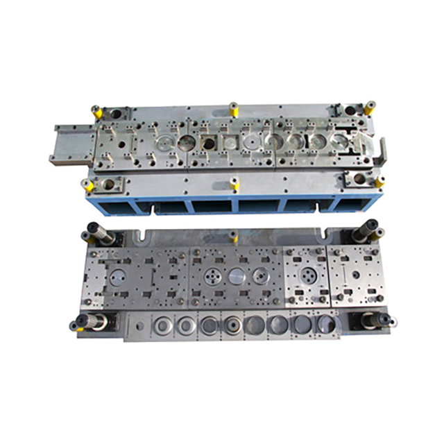
You cannot select a die based on geometry alone. Procurement and engineering teams must conduct a comparative analysis across critical decision-making criteria. Balancing these dimensions ensures the chosen tooling aligns with shop floor realities and capital constraints.
Volume dictates your tooling strategy. You must analyze volume breakpoints to determine when the labor cost of single-stage stamping exceeds the amortization of a progressive die. Single-stage dies dominate low-volume runs, typically under 10,000 units. At this volume, the manual labor required to move parts between presses remains mathematically viable compared to a massive tooling CapEx.
Compound and combination dies fit perfectly into medium-volume production, generally spanning 10,000 to 50,000 units. They offer a middle ground, reducing labor without demanding massive capital expenditure. Progressive dies become the mathematical favorite once volumes exceed 100,000 units. The high speed and automated nature of progressive stamping quickly dilute the initial engineering investment across a massive unit count, driving the per-part cost down to fractions of a cent.
Geometry heavily influences die selection. Progressive dies handle complex 3D geometries, multiple bends, and shallow draws with ease. The multi-station layout allows engineers to unfold complex bends into manageable, sequential steps. However, the carrier strip can stretch slightly as it moves between stations, which can introduce minor tolerance variations on tight-tolerance hole locations.
Compound dies offer superior flatness and concentricity. Because the tool cuts all features simultaneously while clamping the material tightly, the part cannot shift. This eliminates the material distortion often seen in progressive setups. If your print demands strict internal-to-external feature tolerances on a flat plane, compound tooling outperforms progressive tooling every time.
You must break down upfront capital expenditure against long-term operational expenditure. Progressive dies carry significant cost drivers. They require complex CNC machining, wire EDM work, precise pilot pins, lifters, and in-die sensor integration to prevent catastrophic crashes. This complexity drives up the initial investment and requires high-grade tool steels like D2 or carbide inserts for high-wear areas.
Single-stage and compound dies offer simplicity. They require fewer machined components and lack the intricate strip-feeding mechanisms of progressive tools. This simplicity translates directly to speed-to-market. Compound dies are significantly faster to design and build than progressive dies, drastically reducing upfront lead times and allowing you to launch products faster.
Engineering and fabrication lead times vary wildly between die types. A simple single-stage bending die might take two weeks to fabricate. A complex progressive die with twenty stations can require months of design, machining, assembly, and tryout phases. You must factor these lead times into your product launch schedule to avoid missing market windows.
Maintenance risks also scale with complexity. Progressive dies require specialized tool-and-die makers for routine sharpening, sensor calibration, and timing adjustments. A single broken punch or a pulled slug in a progressive die halts the entire production line and can shatter the die block. Single-stage and compound dies are generally easier and cheaper to maintain, requiring less specialized labor for routine upkeep.
Single-stage dies serve a distinct and vital role in manufacturing. You should specify single-stage tooling when facing a low initial budget, a short product lifecycle, or highly uncertain market demand. They also remain the only viable option for extremely large or thick parts that exceed the tonnage capacities of progressive press beds.
Implementing single-stage dies carries specific risks on the production floor. You face a high reliance on operator labor to load, cycle, and unload the press. This manual intervention results in slower throughput. Furthermore, manually repositioning the blank for secondary operations increases the risk of part-to-part variation. Human error during loading can easily push a hole location out of tolerance or result in a scrapped blank.
To mitigate these risks, utilize single-stage dies strategically for initial market testing. Build simple tooling to validate your product design and gauge customer demand. Once order volumes stabilize and dictate faster production, you can execute a planned transition to progressive tooling. This phased approach protects your capital during the riskiest phase of product launch.
Design simple nesting fixtures to help operators locate blanks quickly and accurately.
Implement light curtains and two-hand tie-downs to ensure operator safety during manual loading.
Use standardized die shoes to allow quick changeovers between different single-stage operations on the same press.
Monitor scrap rates closely, as manual handling often leads to higher defect rates than automated feeding.
Compound dies dominate specific niches within metal stamping. Specify a compound die when you have high demand for flat parts requiring tight internal-to-external feature tolerances. Common applications include electrical stators, motor rotors, and precision washers. These parts demand absolute concentricity that sequential cutting in a progressive die struggles to achieve.
The primary value of a compound die lies in its simultaneous cutting action. It completely eliminates the progressive die issue of "walking" or stretching the material between stations. Because the punch and die hold the material perfectly flat during the shear, the resulting parts exhibit exceptional flatness. Furthermore, these dies are less costly and faster to build than their progressive counterparts.
However, compound dies have strict limitations. They cannot accommodate significant bending, forming, or drawing operations. The tooling architecture focuses entirely on shearing. Additionally, scrap removal can sometimes be slower. The knockout mechanism must eject the part and the scrap slug before the next cycle begins, which can limit the maximum strokes-per-minute compared to the continuous flow of a progressive die.
Feature | Compound Die | Progressive Die |
|---|---|---|
Concentricity Control | Exceptional (Simultaneous cut) | Moderate (Subject to strip stretch) |
Part Flatness | Superior (Clamped during shear) | Good (May require flattening stations) |
Production Speed | Medium (Limited by knockout ejection) | Very High (Continuous strip flow) |
Tooling Cost | Moderate | High to Very High |
Forming Capability | None to Minimal (Embossing only) | Extensive (Bends, draws, coining) |
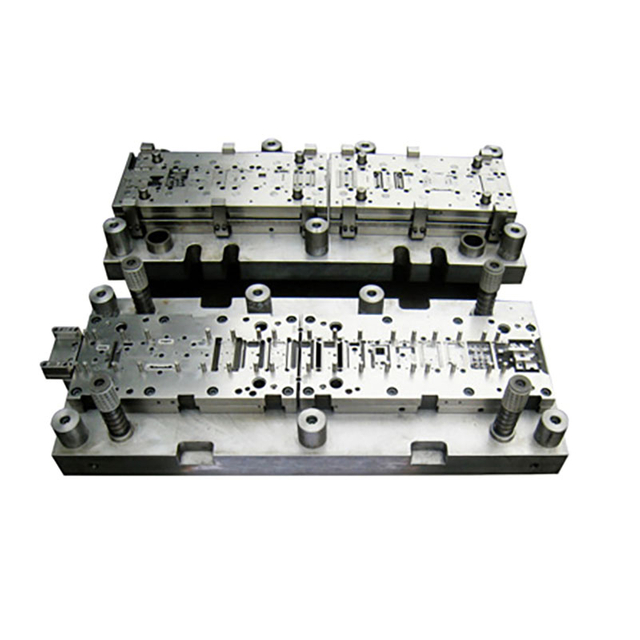
Progressive dies represent the pinnacle of high-volume manufacturing efficiency. You specify progressive tooling for high-volume, multi-feature parts requiring automated, unattended production runs. When you need millions of identical brackets, terminals, or clips with minimal labor intervention, progressive stamping is the definitive answer.
The value proposition of progressive tooling centers on drastic reductions in per-part cost. By integrating multiple operations—coining, punching, bending, and tapping—into one continuous process, you eliminate secondary handling. The press runs continuously, spitting out finished parts at the end of the stroke. This automation maximizes throughput and minimizes direct labor expenses.
The implementation risks involve high upfront costs and longer design lead times. Progressive dies require rigorous Design for Manufacturability (DFM) reviews. You must ensure the carrier strip can physically support the part through all stations without buckling or tearing. Furthermore, these tools are highly vulnerable to catastrophic crashes if the material misfeeds or a slug pulls back up to the die surface.
Mitigation strategies focus on strict process control and sensor integration. You must protect the tool from destroying itself during a high-speed run.
Install proximity sensors to verify the strip has advanced the correct pitch distance before the ram descends.
Utilize acoustic sensors to detect the sound of a pulled slug or a broken punch.
Implement strict preventative maintenance schedules to keep punches sharp and lifters functioning smoothly.
Design robust pilot pins with proper lead-in angles to guarantee absolute strip registration.
Use spring-loaded stock pushers to keep the strip registered against the back guide rail.
When evaluating tooling, you must understand the boundary conditions where standard dies fail. You must differentiate transfer dies and specialized deep draw tooling to complete the evaluation landscape for complex parts. These alternatives step in when progressive or compound dies cannot physically manipulate the material as required by the print.
Transfer dies become necessary when a part is too large for a progressive die strip. If the geometry requires specialized deep drawing, the severe material flow would stretch and break a standard carrier web. In a transfer die setup, the initial station blanks the part completely free from the coil. Mechanical fingers, often operating on a tri-axis servo system, then physically grab the free part and move it between discrete stations.
This approach eliminates the constraints of the carrier web. Material can flow freely into deep draw cavities without tearing the surrounding strip. Transfer dies also optimize material usage, as you do not waste metal on a continuous carrier strip. While slower than progressive dies, transfer systems provide the necessary freedom to manufacture large, deeply formed components like automotive oil pans, appliance housings, or heavy-duty structural brackets.
Procurement and engineering teams need a standardized approach to tooling selection. Guesswork leads to blown budgets, missed tolerances, and broken presses. Follow this step-by-step methodology to align your part design with the correct die architecture.
Define the Geometry: Analyze the part print. Does the part have bends, flanges, or deep draws? If yes, immediately eliminate compound dies from consideration. You must then evaluate combination, progressive, or transfer dies based on the severity of the forming operations.
Calculate the Break-Even Point: Model the labor and cycle time costs of single-stage stamping against the tooling cost and build time of progressive stamping. Determine the exact volume threshold where the automated speed of a progressive die pays for its higher initial build cost.
Assess Press Constraints: Verify your available press bed size, maximum tonnage, and feed equipment capabilities. A massive progressive die requires a large press bed and heavy-duty coil handling equipment. Ensure your facility can physically accommodate the chosen tooling.
Review Material Utilization: Calculate the scrap rate for each die type. Progressive dies waste material on the carrier web, while single-stage and transfer dies can nest blanks tighter. For expensive materials like copper or titanium, material savings might justify a slower die type.
Execute a DFM Review: Engage a tooling engineer early in the process. Optimize the part design for the chosen die type. Small changes to corner radii or hole placements can drastically improve material flow, minimize scrap, and reduce premature tool wear.
Take the following actions to finalize your tooling strategy and protect your production run:
Conduct a formal DFM review with your engineering team to identify features that unnecessarily complicate the tooling architecture.
Run a break-even calculation comparing single-stage labor rates against progressive tooling amortization to ensure your capital deployment matches your production forecast.
Verify your available press bed size, maximum tonnage, and feed equipment capabilities before signing off on the final die design.
Establish strict preventative maintenance schedules and sensor integration plans to protect high-value progressive dies from catastrophic crashes.
For manufacturers looking to improve stamping efficiency and select suitable tooling for different production requirements, Kinglan provides metal stamping equipment and solutions designed to support a wide range of industrial manufacturing applications. With a focus on production efficiency, equipment reliability, and practical manufacturing needs, Kinglan helps customers build more efficient and dependable metal stamping operations.
A: The primary categories include single-stage dies (performing one operation per stroke), compound dies (performing multiple cuts simultaneously on a flat part), combination dies (cutting and forming in one stroke), and progressive dies (moving a continuous strip through multiple sequential stations).
A: You choose a compound die when manufacturing flat parts that require perfect concentricity and extreme flatness, such as washers. Because the material is clamped tightly during the simultaneous cut, it does not stretch or distort, which can happen as a strip moves through a progressive die.
A: While highly dependent on part complexity, progressive dies typically become viable at volumes exceeding 100,000 units. At this threshold, the savings generated by automated, high-speed production offset the significant upfront engineering and machining costs required to build the multi-station tool.
A: Yes, but not in one stroke. Producing a complex part with single-stage tooling requires building multiple separate dies. An operator must manually move the blank from a blanking press, to a piercing press, and finally to a bending press, which significantly increases labor time.
A: A transfer die is used for parts too large or complex for a progressive carrier strip. The first station cuts the blank completely free. Mechanical fingers then physically transfer the loose part between subsequent forming stations, making it ideal for deep draw applications.
A: The carrier web is the continuous strip of uncut material that holds the individual parts together as they advance through the die. It acts as a transport mechanism, allowing pilot pins to align the material precisely at each station before the final cutoff punch separates the finished part.



