
Views: 0 Author: Site Editor Publish Time: 2026-08-10 Origin: Site


Metal stamping floors face tighter tolerances, the rapid integration of advanced high-strength steels, and heavy pressure to cut energy use. You can no longer rely on legacy press technology to push through these production hurdles. Plant managers face a direct conflict between managing upfront capital expenditure and maximizing long-term operational efficiency. You have to decide if the programmable flexibility of a servo press justifies the premium over the proven, reliable mechanical press. Choosing between a mechanical press vs servo press is not about finding a universally better machine. It requires aligning press kinematics, force delivery, energy profiles, and tooling requirements with your specific production line goals. We will break down exactly how these two systems perform on the floor so you can specify the right equipment for your next tooling program and optimize your manufacturing process for the specific parts being stamped.
Table of Contents
Kinematic Control & Force: Servo presses offer infinite control over stroke speed, position, and dwell time with high torque at any speed, whereas mechanical presses operate on a fixed, unalterable stroke profile and force curve driven by a flywheel.
Cost Dynamics: Mechanical presses require significantly lower initial investment; however, servo presses can offset their premium through 32% to 42% lower energy consumption, reduced scrap, and higher output on complex parts.
Tooling Longevity: The programmable slide velocity of a servo press drastically reduces reverse tonnage and die impact, extending tool life compared to standard mechanical presses.
Application Fit: High-volume, simple blanking operations often favor mechanical presses, while deep drawing, in-die tapping, and complex forming of high-strength alloys demand servo technology.
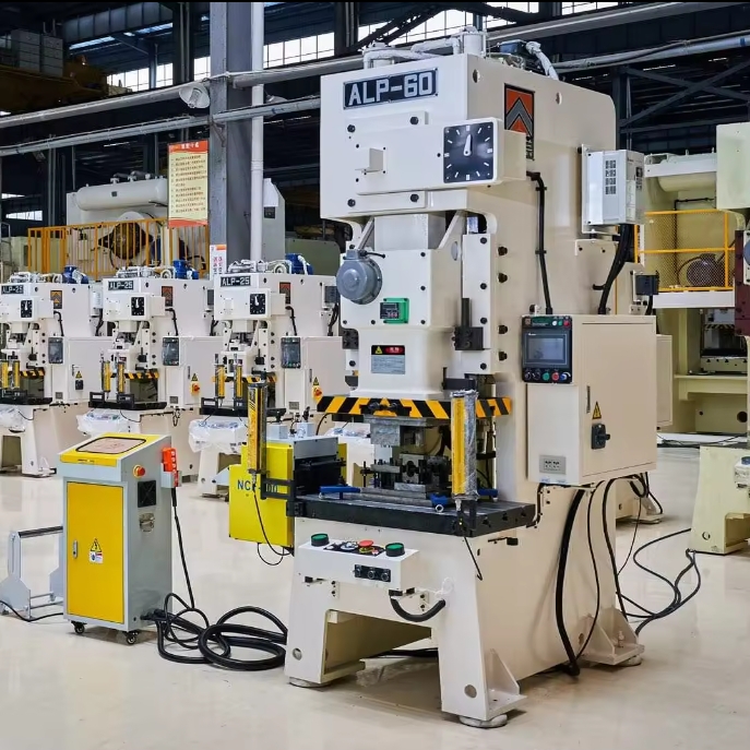
The traditional mechanical press relies on a kinetic energy storage system that has remained fundamentally unchanged for decades. The drivetrain consists of a main AC electric motor that continuously spins a massive cast-iron flywheel. The mass and rotational speed of this flywheel dictate the total available energy for the stamping operation. When the operator initiates a stroke, a pneumatic or hydraulic clutch engages. The friction plates clamp down, connecting the spinning flywheel to the eccentric gear or crankshaft. This mechanical linkage transfers the stored rotational energy into linear motion, driving the ram downward to stamp the part. Once the stroke completes, a brake engages to stop the ram at top dead center.
This physical architecture dictates a fixed stroke length and a rigid, sinusoidal motion curve. The ram accelerates as it moves downward, reaches maximum velocity mid-stroke, and decelerates as it approaches bottom dead center (BDC). You cannot alter this speed profile during the cycle. The press operates at a constant strokes-per-minute rate, and the slide velocity is entirely dependent on that rate. The mechanical linkage means the ram's position is physically tied to the rotary angle of the crank.
Furthermore, mechanical presses have a fixed force limitation based on their mechanical advantage. Full rated tonnage is typically only available very close to BDC, often within the last quarter-inch of the stroke. At 90 degrees, the ram moves at maximum velocity but offers minimal pressing force. If an operation requires high force higher up in the stroke, such as in deep drawing or extruding, a standard mechanical press will stall, slip the clutch, or suffer severe drivetrain damage because it lacks the mechanical leverage at that position.
Servo presses eliminate the flywheel, clutch, and brake entirely. Instead, they utilize a direct-drive or gear-driven high-torque servomotor system coupled directly to the eccentric shaft or drive mechanism. These liquid-cooled motors do not rely on stored kinetic energy. The motor generates torque electromagnetically on demand. The servomotor controls the entire movement of the ram, dictating exact position, velocity, and acceleration at every millimeter of the stroke.
This direct control introduces a fully programmable ram. Operators can program the press to pause at BDC, reverse direction mid-stroke, or change speeds multiple times within a single cycle. The ram can approach the material rapidly, slow down to a crawl right before impact, execute the forming operation at a precise velocity, and then retract at maximum speed to minimize cycle time. The ram's position is tracked by absolute encoders, allowing positional accuracy down to the micron level.
The torque profile of a servomotor provides a massive advantage in force delivery. Unlike a flywheel-driven press that loses energy as it slows down, a servomotor can deliver high torque and full pressing force even at extremely low speeds or during a complete stop. If you need 400 tons of force four inches above BDC, the servomotor draws the necessary current to deliver that torque instantly. This capability allows the press to perform heavy forming operations higher up in the stroke without stalling, offering unprecedented versatility for complex tooling.
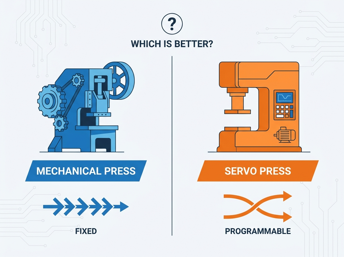
Complex forming operations, particularly those involving advanced high-strength steels or aluminum alloys, require strict control over material flow. Forming materials like DP980 or Martensitic steels presents a unique challenge. These materials work-harden instantly if struck too fast. A mechanical press hits the blank at maximum velocity, causing micro-fractures in the grain structure and leading to premature part failure. Servo presses manage this by slowing the ram velocity to a fraction of normal speed precisely at the point of impact. The press then draws the material at a controlled, constant rate, allowing the metal to flow smoothly into the die cavity without tearing.
Springback is another major quality issue when forming high-strength materials. The programmable nature of the servo drive allows the ram to dwell at BDC for a fraction of a second, holding the material under pressure. This dwell time allows the internal stresses of the metal to relax, setting the structural memory of the part. This significantly reduces springback and ensures the final part meets tight dimensional tolerances without requiring multiple restrike stations.
Contrast this with a mechanical press. The inability to alter speed during the working portion of the stroke means the ram strikes the material at high velocity and immediately begins retracting after hitting BDC. In deep-draw applications, this rapid, unalterable motion often leads to inconsistent part quality, thinning walls, or outright material failure. You are severely limited to simpler geometries when relying on a fixed sinusoidal curve.
While mechanical presses are known for raw speed, servo presses optimize cycle times through intelligent motion paths. One of the most effective techniques is pendulum motion, often referred to as short stroking. Because the servomotor can reverse direction at any point, the ram does not need to complete a full 360-degree rotation. If you are stamping a shallow bracket that only requires two inches of clearance for the transfer system to move the part, a mechanical press with a 12-inch stroke still has to travel the full 12 inches every single cycle.
A servo press can be programmed to only travel 2.5 inches up, reverse, and come back down. You cut out 9.5 inches of wasted travel per stroke. This elimination of wasted motion drastically reduces the time spent cutting air. By only moving the exact distance required to clear the part and feed the next blank, a servo press can take a 30 strokes-per-minute operation up to 60 strokes-per-minute without moving the tool any faster during the actual forming phase.
However, mechanical presses still hold a distinct advantage in specific high-volume scenarios. For continuous, high-speed, full-stroke blanking of simple flat parts, the sheer momentum of a massive spinning flywheel provides unmatched raw speed and reliability. When the operation does not require complex speed variations or short stroking, a mechanical press will often outpace a servo press in pure parts-per-hour output.
Energy efficiency is a critical metric for modern stamping facilities. Servo presses generally consume 32% to 42% less electricity than their mechanical counterparts. A mechanical press requires the main AC motor to run continuously to keep the heavy flywheel spinning. Even during a 20-minute die change, if the motor is left running, it burns kilowatts. It draws substantial power even when the press is idling between strokes.
Servo presses sit completely dead until the cycle starts. They draw power only when the ram is actively moving. When the press stops, power consumption drops to near zero. Furthermore, servo systems utilize regenerative braking. During the deceleration phase of the stroke, the servomotors act as electrical generators. The kinetic energy of the downward-moving ram is converted back into electrical energy and fed into heavy-duty capacitor banks.
These capacitor banks store the regenerated energy and release it during the high-demand acceleration phase of the next stroke. When the ram drives down, it pulls energy from the capacitors rather than directly from the grid. This closed-loop energy management system flattens the peak power draw from the facility's grid. This peak-load shaving means the facility's electrical grid doesn't see massive spikes, resulting in significantly lower demand charges on the utility bill and a smaller carbon footprint for the stamping operation.

Reverse tonnage, or snap-through shock, is one of the most destructive forces in a stamping press. When punching thick, high-tensile material, the press builds up massive pressure. When the material finally shears, that pressure releases instantly. The press frame acts like a giant spring snapping back. This violent shockwave destroys die shoes, chips carbide punches, stretches tie rods, and causes structural fatigue in the press components.
Servo presses mitigate reverse tonnage by programming a soft touch and a controlled breakthrough. The ram slows down just before the material fractures, absorbing the energy release and dissipating the shockwave before it can damage the tooling or press frame. This controlled motion drastically extends die life, increases the number of hits between tool sharpenings, and reduces the frequency of costly maintenance intervals.
Maintenance requirements also differ fundamentally between the two technologies. Mechanical presses rely on wear parts that require regular inspection and replacement. You have to maintain clutch and brake linings, massive pneumatic systems, and complex recirculating lubrication systems for the flywheel bearings. Servo press maintenance shifts away from mechanical wear parts toward electronic diagnostics. You focus on the health of the servo drives, motor cooling loops, and capacitor banks.
Maintenance Component | Mechanical Press Requirement | Servo Press Requirement |
|---|---|---|
Drive Engagement | Replace worn clutch and brake friction linings regularly. | No clutch or brake linings; monitor electronic drive health. |
Energy Storage | Grease and inspect heavy flywheel bearings and belts. | Inspect capacitor banks and verify charge/discharge cycles. |
Cooling Systems | Standard ambient air cooling for main AC motor. | Maintain liquid cooling loops and heat exchangers for servomotors. |
Pneumatics | Extensive air lines and valves required for clutch operation. | Minimal pneumatics required; primarily for counterbalance systems. |
Diagnostics | Physical inspection by millwrights (visual wear, mechanical tolerances). | Software-based diagnostics using oscilloscopes and fault codes. |
The initial purchase cost is the most immediate hurdle when evaluating press technology. Servo presses command a significant premium over an equivalent tonnage mechanical press. This higher initial investment is driven by the massive, liquid-cooled, high-torque servomotors, the sophisticated CNC motion control architectures, absolute encoders, and the high-capacity energy storage banks required to run the machine. These precision electronic components are inherently more expensive to manufacture than traditional cast-iron flywheels and pneumatic clutches.
Installation realities also factor into the initial capital expenditure. Mechanical presses generate severe vibration due to the violent nature of their snap-through shock and the heavy vibration generated by the flywheel and clutch engagement. Facilities often need to pour deeper, reinforced concrete pits and install expensive vibration isolation pads to prevent the shockwaves from affecting nearby CNC mills or CMM machines. Servo presses operate with smooth, controlled motion. While they still require solid foundations, the dynamic loading is significantly lower, which can sometimes reduce civil engineering costs during installation.
Justifying the higher upfront cost of a servo press requires a rigorous analysis of long-term operational expenses. The return on investment calculation must factor in several distinct operational advantages. First, the reduction in energy consumption provides a measurable month-over-month utility saving. Second, the ability to program dwell times allows for in-die secondary operations. If you can program a dwell at BDC, you can integrate in-die tapping, welding, or automated hardware insertion right in the press. You eliminate the need for a secondary workstation, an extra operator, and the associated work-in-progress inventory.
Furthermore, the reduction in scrap rates when forming complex parts accelerates the payback period. Dropping scrap rates from 5% down to 0.5% on expensive aerospace alloys yields massive savings. By running parts faster using pendulum motion, the facility increases overall throughput, generating more revenue per shift from the same footprint.
However, plant managers must approach ROI calculations with caution. Avoid relying on guaranteed payback timelines provided by vendors. The actual return is strictly dependent on part complexity, material types, and shift utilization. If a servo press is purchased to run simple flat blanks on a single shift, the financial return may never materialize. The technology pays for itself only when its advanced capabilities are actively utilized to solve complex stamping challenges.

Mechanical presses remain the backbone of many stamping facilities for good reason. They are the optimal choice for specific applications where programmable motion provides no added value. Specify a mechanical press for:
High-speed, continuous flat blanking operations where raw strokes-per-minute is the only metric that matters.
Simple progressive die stamping where material flow, tearing, and springback are not critical issues.
Operations running high volumes of identical, low-complexity parts that do not require frequent die changes.
Facilities with strict upfront budget constraints where fixed force and speed are sufficient for the current and future product mix.
Environments where in-house maintenance teams are highly experienced with traditional clutch-and-brake systems and lack mechatronics training.
Servo technology becomes necessary when the limitations of a fixed stroke hinder production quality or efficiency. Specify a servo press for:
Deep drawing applications requiring precise material flow control to prevent tearing and wall thinning.
Forming advanced high-strength steels, titanium, or aerospace alloys prone to severe springback and work-hardening.
Complex progressive dies that incorporate in-die tapping, hardware insertion, or welding requiring precise dwell times at the bottom of the stroke.
Job shops that run a high mix of different parts and require maximum versatility and rapid changeovers from a single machine.
Operations looking to maximize output on shallow parts by utilizing pendulum motion to eliminate wasted ram travel.
For facilities that need better drawing capabilities than a standard mechanical press but cannot justify the cost of a full servo system, link motion presses offer a middle ground. These machines use a modified mechanical toggle linkage instead of a standard eccentric crank. The linkage mechanically alters the slide velocity, slowing the ram down significantly during the working portion of the stroke and speeding it up during the return phase.
This mechanical modification provides a gentler impact and better material flow for drawing operations without relying on electronic servomotors. It is a hardware solution to a motion problem. While link motion presses lack the infinite programmability, dwell capabilities, and pendulum motion of a servo press, they provide a cost-effective upgrade for specific forming applications. However, you cannot change the profile. If you switch from a deep draw part to a shallow blanking part, you are stuck with that slow draw speed.
To fully understand the press landscape, you must contrast both mechanical and servo presses with hydraulic presses. Hydraulic presses use fluid pressure driving a cylinder to move the ram. They are ideal for heavy-duty tasks requiring immense, sustained force throughout a very long stroke, such as deep drawing massive automotive body panels or compacting powders. They can deliver full tonnage at any point in the stroke.
However, hydraulic presses are generally slow. A hydraulic press might run at 10 strokes per minute, consume high amounts of energy, and carry the risk of oil leaks and environmental hazards. Servo presses bridge the gap, offering a superior blend of hydraulic-like force control with mechanical-like speed, precision, and cleanliness. A servo press gives you the force profile of a hydraulic press but can run at 40 strokes per minute. While hydraulics still win for ultra-heavy-duty sustained force, servo presses are rapidly replacing them in precision forming applications.
Transitioning from traditional mechanical setups to a servo-driven environment introduces a significant learning curve. Operators accustomed to simply adjusting shut height and setting a continuous speed must now learn to build complex motion profiles on advanced human-machine interfaces. They must understand the relationship between velocity changes, heat generation in the die, material flow, and reverse tonnage.
This transition requires upskilling operators, setup personnel, and tooling engineers. If an operator programs a rapid approach and forgets to decelerate before contact, they will shatter the die. Facilities must invest in comprehensive training to maximize the technology's potential. If the workforce treats a servo press exactly like a mechanical press, running it at a constant speed with a full stroke, the facility will gain zero operational benefit from the massive capital investment.
While servo presses are highly energy-efficient overall, their power draw profile is vastly different from mechanical presses. A servomotor requires massive spikes of electrical current during the acceleration phase of the stroke. If the press is not equipped with adequate energy management systems or active front ends, these peak power draws can severely strain the facility's electrical infrastructure.
Before installation, plant engineers must conduct a thorough power quality analysis. You must ensure the local grid and the facility's transformers can handle the rapid fluctuations in power demand. Voltage drops or dirty power can cause drive faults. You might need to upgrade transformers or install line reactors to protect the servo drives and prevent disruptions to other sensitive CNC equipment on the factory floor.
The shift in technology alters the maintenance paradigm. Mechanical press troubleshooting is often handled effectively by in-house millwrights who understand gears, pneumatic clutches, and lubrication lines. When a mechanical press goes down, the problem is usually visible and physical. You need a technician with a grease gun and a wrench.
Servo presses require a different diagnostic approach. Troubleshooting drive faults, encoder signal errors, or cooling loop flow rates requires specialized mechatronics technicians or electrical engineers. You need a technician with a laptop and an oscilloscope. Facilities adopting servo technology must often rely more heavily on specialized vendor support, remote diagnostics, and software updates, shifting maintenance from mechanical repair to electronic analysis.
To move forward with an equipment upgrade and ensure you select the right press technology for your stamping floor, take the following actionable steps:
Audit your current production runs to identify specific parts with high scrap rates due to springback, tearing, or inconsistent material flow.
Map out the required tonnage curves for your most complex dies to determine if they exceed the capacity of your existing mechanical presses higher up in the stroke.
Evaluate your facility's electrical infrastructure, specifically transformer capacity and power quality, to ensure compatibility with the peak power demands of servo drive systems.
Consult with your tooling department to determine which progressive dies could incorporate in-die tapping or automated assembly if provided with programmable dwell times.
Founded in 1983, Zhejiang Jinaolan Machine Tool manufactures mechanical presses and integrated stamping-line equipment in capacities ranging from 25 to 2,400 tons. Its experience in press manufacturing, automated feeding systems, stamping dies, transfer equipment, and production-line integration can help manufacturers evaluate equipment configurations for different materials, tooling programs, and output targets.
A: The primary difference is the drive mechanism. A mechanical press relies on a continuously spinning flywheel and a clutch to drive the ram, creating a fixed, unalterable stroke and speed profile. A servo press uses a direct-drive servomotor, which eliminates the flywheel and allows for a fully programmable stroke, variable speeds, and precise dwell times at any point in the cycle.
A: Yes, servo presses typically consume 32% to 42% less energy. Mechanical presses draw continuous power to keep the heavy flywheel spinning, even when idling. Servo presses only draw power when the ram is actively moving. They also utilize regenerative braking, where the servomotors act as generators during deceleration, feeding energy back into the system's capacitor banks.
A: In many precision forming applications, yes. Servo presses provide the same ability to deliver full tonnage at any point in the stroke, which is the primary advantage of a hydraulic press. However, servo presses operate at much higher speeds, offer superior positional accuracy, and eliminate the environmental hazards and maintenance issues associated with hydraulic oil leaks.
A: The initial investment is higher due to the advanced technology required to build the machine. Servo presses rely on massive, liquid-cooled, high-torque servomotors, sophisticated CNC motion control architectures, absolute encoders, and heavy-duty capacitor banks for energy management. These precision electronic components are inherently more expensive to manufacture than traditional cast-iron flywheels and pneumatic clutches.
A: A servo press extends tooling life by controlling the exact velocity of the ram at the point of impact. By programming the press to slow down just before contacting the material, it drastically reduces impact shock. It also controls the breakthrough speed during punching operations, minimizing the destructive reverse tonnage that normally causes premature wear on punches and die shoes.
A: Reverse tonnage is the violent negative force generated when material suddenly fractures during a punching or blanking operation. This sudden release of pressure sends a damaging shockwave through the press. Servo presses handle this by decelerating the ram precisely at the point of material fracture, absorbing the energy release and dissipating the shockwave before it can damage the tooling or press frame.



