
Views: 0 Author: Site Editor Publish Time: 2026-08-24 Origin: Site


Procuring a complete stamping production line represents a massive capital expenditure for any manufacturing facility. It demands rigorous planning, deep engineering alignment, and strict technical precision. A generic request for quotation often leads to mismatched vendor proposals and chaotic project execution. You face hidden integration issues, dangerous scope creep, and equipment that consistently misses performance targets. A poorly defined scope leaves communication gaps between the main press, the transfer automation, and the coil handling systems. You need a rigorously structured stamping line RFQ to mitigate these operational risks. This framework translates your specific production requirements into strict vendor evaluation criteria. We will cover exact technical specifications, facility constraints, and commercial terms to ensure your next major equipment purchase runs flawlessly from installation to full-rate production.
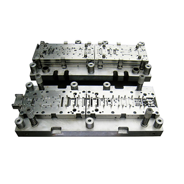
A successful stamping line RFQ must treat the press, coil handling, and automation as an integrated system rather than isolated components.
Precise material specifications (including advanced high-strength steels) and facility constraints (foundation pits, crane capacities) are non-negotiable data points for accurate quoting.
Structuring the RFQ process—from NDA execution to standardized response templates—is critical for conducting an objective, apples-to-apples vendor comparison.
Vendor evaluation should prioritize controls integration capabilities, and proven project management over the lowest initial bid.
Clear definitions of Factory Acceptance Testing (FAT), Site Acceptance Testing (SAT), and commercial performance guarantees must be established within the RFQ to ensure accountability.
Table of Contents
Assemble a cross-functional internal team before drafting any procurement documents. This team must include engineering, maintenance, environmental health and safety (EHS), and procurement personnel. Each department brings operational insights to the table. The tooling engineer defines the stroke kinematics, shut height, and tonnage parameters based on current and future die designs. The maintenance manager highlights serviceability requirements, demanding easy access to lubrication manifolds, clutch assemblies, and main drive motors. EHS ensures compliance with local safety regulations, specifying sound enclosures and ergonomic operator stations. Procurement manages the commercial timeline and vendor communications. Together, they define the exact project scope and prevent change orders later in the build cycle.
Next, identify a shortlist of three to five highly qualified suppliers. Look for vendors with proven experience in turnkey systems integration. You need partners who can handle the entire production ecosystem, not just individual standalone machines. Execute Non-Disclosure Agreements (NDAs) with these shortlisted suppliers immediately. NDAs protect your proprietary part designs, die blueprints, and annual production volumes during the vulnerable quoting phase. Do not share a single CAD file until the legal department clears the signed NDA.
A professional RFQ package contains several components to ensure clarity and force standardized responses. It starts with a formal cover letter outlining the project timeline, site visit dates, and final submission deadlines. Next is the comprehensive technical specification document detailing every mechanical, electrical, and software requirement. You also need a dedicated section outlining all expected commercial terms, delivery expectations, and warranty requirements. Finally, include a standardized pricing response template in spreadsheet format. This template forces vendors to break down their costs uniformly across specific categories, preventing them from hiding numbers in lump-sum bids.
Schedule a formal Q&A period immediately after issuing the package. Mandate physical site visits for all participating vendors. They need to see the facility constraints, existing foundation pits, and overhead crane limitations firsthand. Document every technical question asked during these site visits. Distribute the answers to all vendors simultaneously via formal addendums. This ensures everyone receives identical clarifications and maintains a strictly level playing field.
RFQ Document Component | Primary Purpose | Required Format |
|---|---|---|
Technical Specifications | Defines machine dimensions, speeds, capacities, and controls architecture. | PDF / Word Document |
Part Prints & 3D Models | Allows vendors to calculate tonnage, off-center loading, and transfer pitch. | STEP / IGES / DWG |
Plant Layout | Shows floor space, structural columns, aisles, and crane locations. | DWG / DXF |
Pricing Template | Forces itemized cost breakdowns for objective bid normalization. | Excel Spreadsheet |
Commercial Terms | Outlines payment milestones, delivery penalties, and warranty periods. | PDF Document |
Receiving the vendor bids is only the beginning of the evaluation phase. You must normalize these proposals for a truly objective analysis. Normalization involves stripping away marketing language and sales terminology. You align each vendor's proposed deliverables, line item by line item. Compare their defined battery limits and explicit project exclusions side-by-side to find the gaps.
One vendor might include full foundation engineering, pit construction, and isolation pads. Another vendor might exclude civil works entirely, leaving that massive undertaking to your facility team. Normalizing the bids reveals the true total scope of each proposal. You must add the estimated cost of excluded items back into the incomplete bids. If Vendor A excludes rigging and Vendor B includes it, you must add your local rigger's quote to Vendor A's column. This rigorous process prevents financial surprises during the installation phase.
Standard manufacturing RFQs often focus entirely on single-machine specifications. You might buy a standalone CNC mill or a single press brake with isolated parameters. A complete stamping line operates under entirely different rules. It is a highly synchronized manufacturing ecosystem. Every machine must communicate with the equipment upstream and downstream in real-time.
The line requires millisecond-level handshakes between multiple heavy components. The uncoiler feeds raw material to the precision straightener. The straightener removes coil set and prepares the strip, feeding it into a loop pit. The servo feeder pulls from this loop, pushing exact material lengths into the press die during a specific window of the press stroke. The press controls must synchronize perfectly with the automated transfer system. The transfer rails must enter the die space, grip the part, move it to the next station, and exit before the upper die descends. Meanwhile, the scrap conveyor must remove offal at the exact rate of continuous production to prevent jams.
Your RFQ must force vendors to quote a complete turnkey solution. If you choose to use multiple specialized vendors, the document must explicitly define the battery limits. Who handles the mechanical integration between the servo feeder and the press bed? Who integrates the emergency stop safety circuits across all machines? A systems-level approach guarantees that all components communicate flawlessly and operate safely without finger-pointing between suppliers.
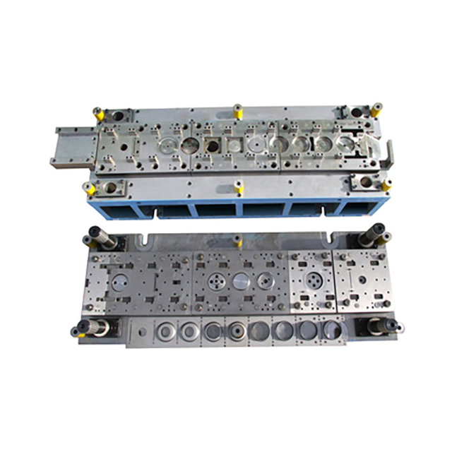
Vendors cannot design a robust mechanical system without exact part data. Provide accurate 3D CAD models and detailed 2D part prints. These files dictate the required die design, shut height, and transfer automation requirements. They allow the vendor to run forming simulations to verify tonnage requirements, reverse tonnage (snap-through), and off-center loading forces.
Material specifications dictate the structural integrity of the entire feed line. Detail the exact yield strength, ultimate tensile strength, and elongation properties of your stock. Provide strict thickness ranges from minimum to maximum. Specify the minimum and maximum coil width you plan to run. Include the maximum allowable coil weight and the maximum outside diameter (OD) and inside diameter (ID) of the coils.
Advanced High-Strength Steels (AHSS) and aluminum drastically impact equipment design. AHSS requires significantly higher press tonnage to overcome massive snap-through forces. It also demands specialized straightener roll configurations—specifically smaller diameter rolls spaced closely together with heavy-duty backup flights—to yield the material and remove severe coil set. Aluminum requires specific polyurethane-coated handling equipment and threading tables to prevent surface marring. Document these specific material properties clearly in the RFQ.
Define your target production volumes clearly for each shift. Specify the required Strokes Per Minute (SPM) for each distinct part family. Do not just state a theoretical maximum SPM. Provide the required continuous operating speed for daily production. The equipment must sustain this speed without overheating the clutch, faulting the servo motors, or vibrating out of tolerance.
Specify acceptable Overall Equipment Effectiveness (OEE) thresholds. Define the maximum allowable scrap rates during steady-state production. These specific metrics form the absolute basis of your commercial performance guarantees. If the vendor claims the line will run at 40 SPM, they must prove it during the runoff testing.
Outline your strict die changeover time requirements. If you require Single-Minute Exchange of Die (SMED) capabilities, state it clearly. Specify if you need moving bolsters (T-track or dual rolling), automated hydraulic die clamping, or robotic tool changers. Fast, repeatable changeovers directly impact your stamping line's overall profitability and uptime. Detail the exact sequence you expect the operators to follow during a changeover.
List the critical press dimensions required to house your largest dies. Specify the necessary continuous tonnage and where that tonnage must be available in the stroke. Define the exact bed size, including left-to-right and front-to-back dimensions. Detail the required stroke length, shut height, and motorized slide adjustment range. Specify the maximum allowable deflection (e.g., 0.0015 inches per foot) and tie-rod stretch limits.
Specify the exact type of press drive required for your parts. Mechanical link-drive presses suit high-speed blanking and shallow forming, slowing down the slide during the working portion of the stroke. Servo presses offer fully programmable stroke profiles, allowing you to dwell at the bottom for complex, deep forming applications or in-die tapping. Hydraulic presses provide full tonnage throughout the entire stroke for deep drawing. You can also request vendors to propose and mathematically justify the best drive option based on your part prints.
Define your feed line requirements based on available floor space and material thickness. Space-saving compact feed lines work well for moderate thicknesses and tight layouts. Conventional loop lines require significantly more room, often necessitating a concrete loop pit, but they handle heavy gauge materials much better by decoupling the straightener speed from the feeder speed. Specify the required mandrel expansion range for the uncoiler and whether you need a coil car for loading.
Specify your exact transfer automation needs. Do you need robotic tandem lines for moving large automotive panels between multiple presses? Are you using high-speed in-press transfer systems for progressive dies? Define the maximum payload, transfer pitch, clamp stroke, and lift requirements for these automated systems. Specify if you need double-blank detection sensors or programmable part-tracking sensors.
Include strict requirements for all auxiliary support equipment. Specify how scrap shedding should operate beneath the bolster, detailing the required scrap chute angles and shaker conveyor dimensions. Define the part outfeed mechanisms and inspection conveyors. Mandate automated, programmable lubrication systems for both the machine components and the stock material to extend die life and reduce manual maintenance tasks.
Never assume a vendor understands your specific building constraints. Provide a highly detailed plant layout in DWG format with your stamping line RFQ. This engineering layout must show structural columns, forklift aisles, pedestrian walkways, and adjacent machinery. It must highlight the exact proposed footprint for the new equipment, including maintenance access zones.
List all critical facility structural data. Specify the exact ceiling clearance height. Note the overhead crane hook height and its maximum lifting capacity. Detail the concrete floor loading limits and the underlying soil bearing capacity. If you have existing foundation pits, provide their exact dimensions and structural rebar drawings. If the vendor must design a new foundation, they need the soil data to determine if standard pads or deep micro-piles are necessary. Specify if you require spring isolation pads to mitigate vibration transfer to the rest of the plant.
Specify the available plant power at the installation site. Include the exact voltage, frequency, and maximum available amperage. Detail your compressed air capacity in CFM and PSI, and specify if the vendor needs to supply local surge tanks to prevent pressure drops during clutch engagement. Note the availability, flow rate, and temperature of industrial cooling water. The vendor needs this data to size heat exchangers, hydraulic power units, and main drive motors.
Mandate strict compliance with regional industrial safety standards. In the United States, require absolute adherence to OSHA and ANSI B11.1 standards for mechanical power presses. In Europe, mandate full CE marking and documentation. Specify the required guarding methods. Detail exactly where you expect safety light curtains, laser area scanners, and interlocking hard fencing. Safety compliance is an absolute requirement, and the RFQ must state that the vendor is responsible for passing a third-party safety audit before final sign-off.
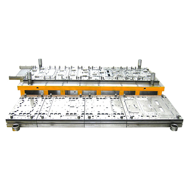
Require vendors to specify their proposed PLC and HMI hardware architecture. If your plant runs entirely on Allen-Bradley or Siemens platforms, state this requirement explicitly. The new stamping line must integrate with your existing plant networks and maintenance inventory. Mixing control platforms creates massive headaches for your electrical technicians and requires stocking duplicate spare parts.
Define your data collection and Industry 4.0 connectivity requirements. Specify the need for predictive maintenance sensors on critical eccentric bearings, clutch housings, and main motors to monitor vibration and temperature. Mandate integration capabilities with your Enterprise Resource Planning (ERP) or Manufacturing Execution System (MES) via protocols like OPC UA or Ethernet/IP. The equipment must push real-time production data, fault codes, and stroke counts automatically to your central servers.
Clearly delineate all installation and rigging responsibilities. State exactly who unloads the heavy equipment from the flatbed trucks. Specify who provides the specialized rigging services, heavy forklifts, and gantry cranes. Define who handles the primary electrical drop, main pneumatic connections, and foundation epoxy grouting. Ambiguity in installation responsibilities causes schedule delays and budget overruns.
Specify the required duration and technical scope of training. You need dedicated, separate sessions for machine operators and maintenance technicians. Operator training should cover daily use, HMI navigation, fault recovery, and safe die changeovers. Maintenance training must cover deep electrical troubleshooting, reading the specific ladder logic, preventative mechanical care, and software diagnostics.
Detail your required commercial stipulations clearly to avoid negotiation bottlenecks. Establish standard, milestone-based payment structures. A common and fair structure is a down payment with the purchase order, a progress payment upon major component casting, a payment after successful FAT, and the final holdback after successful SAT. Never pay the full balance before the equipment produces good parts in your facility.
Define the delivery terms using standard Incoterms like DDP (Delivered Duty Paid) or DAP (Delivered at Place). Establish clear financial penalties for missed delivery deadlines. Use liquidated damages clauses to enforce the project schedule strictly. Tie final payments directly to commissioned performance metrics. If the line fails to hit the promised SPM or OEE during the site runoff, the vendor must engineer a correction at their own expense before receiving final payment.
Create a weighted scoring matrix to evaluate vendors objectively. Score them based on their strict adherence to your RFQ specifications. Did they meet the required tonnage, bed size, and speed requirements? Did they include the requested safety PLC platform? Did they size the straightener rolls correctly for your AHSS material? Score each line item to remove emotion and brand bias from the purchasing decision.
You must also evaluate alternative engineering proposals carefully. Sometimes a vendor suggests a different technology to achieve the exact same outcome. They might propose a servo press instead of a mechanical one to improve part quality on a difficult draw, or a compact feed line instead of a loop pit to save foundation costs. Evaluate these alternatives objectively. Ask the vendor to provide simulation data and kinematic charts proving the alternative method yields better results or higher efficiency.
Factory Acceptance Testing (FAT) and Site Acceptance Testing (SAT) validate the equipment performance. Define the exact testing protocols in the RFQ document. FAT occurs at the vendor's assembly facility before shipping. You ship your actual dies and raw material coils to their floor. You verify the SPM, part quality, transfer timing, and all basic safety interlock functions. The machine does not ship until you sign the FAT approval document.
SAT occurs at your facility after complete installation, rigging, and leveling. This test proves the equipment works in its final production environment, connected to your plant utilities. You run a continuous production batch for a specified duration, often 8 to 24 hours. You measure actual OEE, scrap rates, and die changeover times under real-world conditions. Final acceptance and the release of the final payment depend entirely on passing the SAT parameters.
A well-structured stamping line RFQ turns complex production requirements into clear technical, commercial, and performance expectations for potential suppliers. By defining equipment specifications, automation interfaces, facility conditions, project responsibilities, and acceptance criteria from the beginning, manufacturers can compare proposals more accurately and reduce integration risks, unexpected costs, and commissioning delays. Kinglan focuses on metal forming and stamping equipment solutions, supporting manufacturers with press machinery and related production technologies for a range of industrial applications and integrated stamping requirements.
Assemble your cross-functional team immediately to define the exact mechanical, electrical, and safety scope before contacting any suppliers.
Gather all necessary 3D part models, material yield specifications, and facility layout drawings to build a comprehensive engineering data package.
Draft a standardized pricing template to force vendors into an itemized format, enabling objective bid normalization and exposing hidden exclusions.
Establish clear performance metrics, including target SPM and OEE, to serve as the baseline for your SAT runoff and final payment release.
A: The most common mistake is failing to define the battery limits between different equipment vendors. If the press manufacturer and the automation supplier do not know who is responsible for the physical and electrical integration, you will face severe delays and unexpected costs during installation.
A: Vendors need 3D models to run accurate forming simulations. This data allows them to calculate the exact tonnage requirements, off-center loading forces, and the necessary transfer pitch for the automation system. Without it, they are forced to guess, leading to oversized or undersized equipment.
A: If you have a specific requirement based on legacy dies, you should dictate it. However, it is often beneficial to outline your part requirements and ask vendors to propose the best drive technology. They might suggest a servo drive that improves your part quality significantly.
A: A standard Q&A period for a complex stamping line should last two to three weeks. This gives vendors enough time to review the technical specifications, conduct a site visit, consult with their engineering teams, and formulate detailed questions regarding facility constraints.
A: FAT (Factory Acceptance Testing) occurs at the vendor's facility to ensure the machine functions properly before shipping. SAT (Site Acceptance Testing) occurs at your facility after installation. SAT proves the equipment meets production speeds and quality metrics in its actual operating environment.
A: You must execute a Non-Disclosure Agreement (NDA) with every participating vendor before sharing any part prints, 3D models, or production volume data. This legal document protects your intellectual property while allowing vendors to engineer the correct mechanical solution.



