
Views: 0 Author: Site Editor Publish Time: 2026-08-10 Origin: Site


Acquiring a power press represents a high-stakes capital expenditure where precision dictates profitability. Over-speccing the equipment wastes allocated budget and inflates facility requirements, while under-speccing destroys expensive tooling, produces unacceptable scrap rates, and ultimately halts production. Manufacturing environments demand equipment that perfectly aligns with specific operational parameters.
Matching press capabilities to production needs involves far more than simply looking at tonnage. Production managers and manufacturing engineers must evaluate a complex matrix of variables, including frame rigidity, slide velocity, drive architecture, and material characteristics like gauge and tensile strength. Treating press size as the sole decision metric inevitably leads to catastrophic equipment failure or severe operational bottlenecks.
This evaluation framework provides a systematic approach to aligning sheet metal stamping requirements with the correct machine architecture. By analyzing material behavior, production volumes, and facility constraints, engineering teams can specify equipment that guarantees consistent part quality and maximizes tooling longevity.
Table of Contents
Tonnage is a baseline, not a conclusion: Calculating required punch capacity must account for material shear strength, part perimeter, and a 20% safety margin to prevent premature press wear.
Drive type dictates application: Mechanical presses dominate high-speed blanking, while hydraulic presses provide the sustained force required for deep drawing.
Frame rigidity impacts tooling life: Straight-side frames offer superior deflection resistance compared to C-frames, directly reducing die maintenance costs in high-tolerance applications.
Long-term economics extend beyond the machine: Facility foundation requirements, automation compatibility, and energy consumption profiles heavily influence long-term ROI.
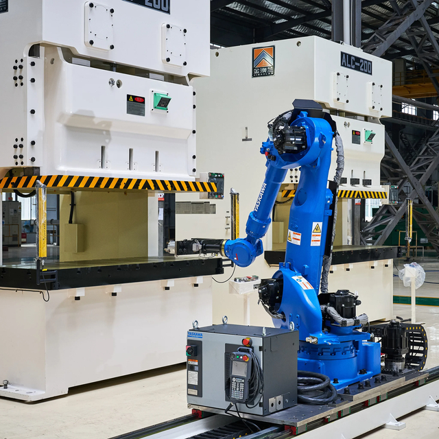
Selecting the appropriate equipment begins with a rigorous analysis of the parts you intend to manufacture. Every characteristic of the raw material and the finished component heavily influences the required mechanical specifications of the stamping equipment. You cannot specify a machine without first understanding exactly what it will be hitting, how fast it needs to hit it, and what tolerances the final part must hold.
The physical properties of the metal dictate the baseline force required to deform or shear it. Different materials exhibit vastly different shear and yield strengths. Stamping standard 1.8mm commercial mild steel requires a predictable force profile. However, attempting to process 1.8mm advanced high-strength steel (AHSS) or dual-phase alloys demands significantly higher tonnage and massive structural rigidity to overcome the material's extreme resistance to deformation.
Aluminum presents a completely different set of challenges. While softer and requiring less raw tonnage, aluminum is prone to galling and tearing during forming operations. It often requires specialized stroke profiles and precise slide velocity control to allow the material to flow properly into the die cavity. Engineering teams must document the maximum material thickness, maximum tensile strength, and maximum shear strength for all current and future production runs before evaluating any machinery.
Material Type | Typical Yield Strength (MPa) | Forming Characteristics | Press Requirement Impact |
|---|---|---|---|
Commercial Mild Steel | 150 - 250 | Highly ductile, predictable flow | Standard tonnage and frame rigidity sufficient. |
Aluminum Alloys (e.g., 6061) | 275 - 300 | Prone to galling, requires lubrication | Requires precise velocity control to prevent tearing. |
Advanced High-Strength Steel (AHSS) | 500 - 1000+ | High springback, extreme resistance | Demands high tonnage, rigid straight-side frames, and shock absorption. |
Stainless Steel (e.g., 304) | 215 - 505 | Work-hardens rapidly during forming | Requires sustained force and slower drawing speeds. |
Throughput requirements establish the necessary operational speed, measured in Strokes Per Minute (SPM). Low-volume custom runs prioritize quick die changes, accessible bed areas, and setup flexibility over raw speed. Conversely, high-volume continuous production demands equipment optimized for rapid, uninterrupted cycling and automated material feeding.
Heavy forming and deep drawing operations require slower speeds, typically ranging from 10 to 18 SPM. This slower velocity allows the material sufficient time to stretch and flow over the punch without fracturing. Standard high-speed blanking operations generally run between 125 and 250 SPM. For ultra-high-speed blanking applications, such as stamping electrical motor laminations, specialized equipment can achieve up to 1800 SPM. Running a machine at its absolute maximum SPM constantly will degrade the clutch and brake systems prematurely, so engineers typically specify a machine capable of 20% higher speeds than the target production rate.
The intended metalworking operation restricts your equipment options. Blanking and piercing operations involve shearing the metal. This requires a sudden, high-impact force exactly at the bottom of the stroke. Coining requires massive force over a very short distance to compress the metal into a specific shape, demanding extreme frame rigidity to prevent the press from stalling.
Deep drawing requires sustained, uniform pressure throughout a long stroke to pull the metal into a die cavity without wrinkling or tearing the side walls. Progressive die stamping, where a strip of metal feeds through multiple stations in a single die block, requires exceptional precision. The machine must maintain perfect alignment across all stations simultaneously, necessitating highly rigid frames and precise feed timing integration.
Finished part tolerances directly dictate the required precision of the equipment. Strict accuracy requirements demand highly rigid frames that resist deflection under load. When a frame deflects, the punch and die lose alignment. Even a misalignment of a few thousandths of an inch leads to out-of-tolerance parts, accelerated die wear, and excessive scrap.
High-precision applications require advanced slide guiding systems. Standard four-point gibs might suffice for basic blanking, but tight-tolerance progressive dies require eight-point gib guiding systems to maintain strict parallelism between the slide and the bed throughout the entire stroke. Cost-efficient metal stamping relies on minimizing scrap and extending die maintenance intervals, both of which depend heavily on the inherent accuracy and rigidity of the chosen machine.

The drive system determines how energy is stored, transmitted, and applied to the workpiece. Understanding the mechanics of each drive type is essential for matching the machine to the specific demands of your stamping operations. Selecting the wrong drive architecture guarantees production bottlenecks and premature equipment failure.
Mechanical systems utilize an electric motor to spin a large, heavy flywheel, storing kinetic energy. When the operator or automation system initiates a stroke, a pneumatic or hydraulic clutch engages, connecting the spinning flywheel to a crankshaft or eccentric shaft. This shaft converts the rotary motion into the linear, up-and-down motion of the slide. A heavy-duty brake stops the slide at the top of the stroke when the clutch disengages.
These machines dominate high-speed blanking, shallow forming, and progressive die operations due to their rapid cycle times and reliable energy delivery. Standard capacities typically range between 30 and 600 tons. The primary limitation of a mechanical drive is that maximum rated force is only available near the bottom dead center (BDC) of the stroke. If your operation requires high tonnage high up in the stroke, a mechanical press will stall. Additionally, the stroke length is fixed, and the slide velocity cannot be adjusted mid-stroke.
Hydraulic systems generate force using fluid pressure. An electric motor drives a hydraulic pump, which forces pressurized oil into large overhead cylinders. The pressure against the cylinder pistons drives the slide downward. Directional proportional valves control the flow of fluid, determining the exact direction and speed of the stroke.
These systems excel in deep drawing, complex forming, and applications requiring full, maximum tonnage throughout the entire stroke length. Because the force is generated by fluid pressure rather than a mechanical linkage, the stroke length is fully adjustable, and the press cannot be mechanically overloaded. However, hydraulic machines generally operate at slower SPM compared to mechanical counterparts. They also introduce the potential for fluid leaks, require heat exchangers to keep the oil cool, and demand diligent maintenance of pumps, valves, and seals.
Servo technology replaces the traditional flywheel, clutch, and brake with a high-torque, direct-drive servo motor connected directly to the drive shaft. This architecture provides absolute control over the slide's position, velocity, and force at every fraction of a millimeter throughout the stroke.
Servo systems are ideal for high-precision forming, processing complex materials like AHSS, and applications requiring variable slide velocity. Operators can program complex stroke profiles. For example, the slide can approach the material rapidly, slow down drastically during the actual forming phase to prevent tearing, dwell at the bottom to reduce material springback, and then retract rapidly. They can also operate in pendulum mode, taking short strokes without returning to top dead center, which massively increases SPM for shallow forming. The primary limitation is the significantly higher upfront capital expenditure and the requirement for specialized maintenance personnel trained in advanced servo electronics.
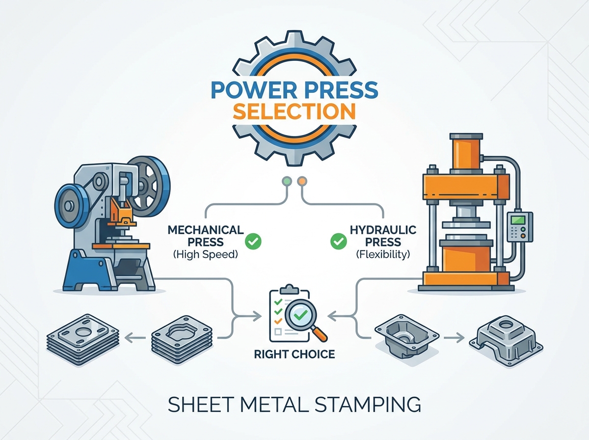
Evaluating specific machine configurations requires translating your production criteria into mechanical specifications. This involves precise calculations, a thorough understanding of structural engineering principles, and a realistic assessment of your tooling inventory.
Determining the exact force required to shear or form a part prevents catastrophic equipment failure. Guessing tonnage based on previous jobs is a fast track to broken crankshafts and shattered dies. For cutting and blanking operations, the standard formula for calculating required force is straightforward: Perimeter of the cut × Material Thickness × Material Shear Strength.
However, this baseline calculation is insufficient for specifying a power press. Engineers must factor in stripping force. When the punch drives through the metal, the material grips the punch tightly. The force required to pull the punch back out of the material typically adds 10% to 20% to the total tonnage requirement. Furthermore, applying a standard safety factor of 20% to 30% ensures the machine operates comfortably within its limits, preventing motor strain and structural fatigue.
Another critical factor is "reverse tonnage" or snap-through shock. When a punch breaks through high-strength material during a heavy blanking operation, the sudden release of stored energy sends a violent shockwave back up through the slide and frame. Excessive reverse tonnage destroys bearings, cracks frames, and shatters carbide tooling. Specifying a machine with adequate mass, heavy-duty tie rods, and specific shock-absorption capabilities mitigates this destructive force.
The structural frame must withstand massive, repeated forces without bending or twisting. The two primary frame architectures offer distinct advantages and severe trade-offs depending on your operational priorities.
C-frame machines feature a frame shaped like the letter "C," leaving the front and both sides completely open. This design provides excellent three-sided access for manual feeding, easy die changes, and accommodates wide or awkwardly shaped parts that extend beyond the bed. They also require a smaller footprint on the shop floor, making them ideal for crowded facilities.
The critical trade-off is angular deflection. Under heavy loads, the open front of the "C" tends to open slightly—a phenomenon known on the shop floor as "yawning." Even a few thousandths of an inch of yawning throws the punch and die out of alignment. This misalignment accelerates die wear, causes burrs on finished parts, and severely compromises accuracy requirements in high-tolerance applications. C-frames are best suited for lighter tonnage, center-loaded blanking, and shallow forming.
Straight-side frames consist of a heavy bed, a top crown, and two vertical side uprights, forming a closed "O" shape. Four massive steel tie rods run vertically through the entire assembly. During installation, these tie rods are heated and the nuts are tightened. As the rods cool and contract, they place the entire frame under massive compression. This pre-loaded four-pillar support system virtually eliminates angular deflection.
Straight-side machines maintain strict parallelism between the slide and the bed, even under maximum off-center loading. They are absolutely essential for high-tonnage applications, progressive die operations, and any process demanding extreme precision. The trade-offs include restricted access to the tooling area (typically limited to the front and rear windows) and a significantly larger physical footprint.
Physical dimensions dictate whether a specific die will fit and function within the machine. Overlooking these dimensions during the specification phase renders the equipment useless for your existing tooling.
Stroke length is the total distance the slide travels from top dead center (TDC) to bottom dead center (BDC). The stroke must be long enough to clear the depth of the formed part and provide sufficient space for automated part ejection and material feeding. If the stroke is too short, the part cannot be removed from the die.
Shut height is the distance from the top of the bed to the bottom of the slide when the stroke is at BDC and the slide adjustment is all the way up. This dimension determines the maximum height of the die block that can be installed. Engineers must verify die space compatibility, accounting for the thickness of any bolster plates or quick-die-change systems.
Bed size (left-to-right and front-to-back dimensions) must accommodate current tooling dimensions while allowing room for future, potentially larger progressive dies. Undersized beds lead to tooling overhang. When a die overhangs the bed, it causes uneven loading, severe frame stress, and rapid degradation of the slide gibs.

Modern stamping operations rely heavily on automation to achieve cost-efficient production. Standalone manual presses are increasingly rare in high-production environments. The chosen machine must seamlessly integrate with peripheral equipment.
Feeding systems, including heavy-duty uncoilers, powered straighteners, and servo-driven coil feeders, must synchronize perfectly with the machine's cycle. Engineers must evaluate the control architecture to ensure seamless communication between the press encoder and the feed line. If the feeder pushes material while the die is still closed, it causes a catastrophic die crash.
Secondary capabilities often dictate the final equipment choice. Knockouts assist in ejecting parts from the upper die half. Die cushions, installed in the bed, provide controlled upward pressure during deep drawing operations to hold the blank flat and prevent wrinkling. Advanced setups may require integration with in-die tapping units, part transfer systems, or automated scrap removal conveyors. The equipment must possess the necessary mechanical interfaces, pneumatic ports, and control logic to support these critical functions.
Specifying industrial machinery requires balancing immediate capital outlay against long-term operational metrics. Engineering teams must evaluate how different architectures impact overall production efficiency and facility overhead.
Standard mechanical configurations represent a lower initial capital expenditure compared to advanced servo-driven alternatives. For dedicated, high-volume blanking of simple parts using mild steel, a mechanical setup provides rapid, reliable output. However, servo technology offers unmatched versatility. The ability to program exact stroke profiles reduces scrap rates on complex materials, minimizes secondary finishing operations, and allows a single machine to perform tasks that might otherwise require multiple dedicated machines. The higher initial cost of a servo press is often offset by the elimination of downstream processing steps.
Different drive systems exhibit distinct energy consumption characteristics. A mechanical flywheel draws continuous power to maintain its rotational mass, even when idling between strokes or during die changes. In contrast, hydraulic and servo systems utilize power on-demand, drawing significant current only during the actual forming stroke. Facilities with strict energy consumption targets must evaluate these profiles against their specific production schedules. Servo presses often incorporate energy recovery systems, storing braking energy in capacitor banks to use during the next stroke, significantly flattening peak power demands.
Tooling represents a massive ongoing expense in metal stamping. High-quality carbide progressive dies can cost tens or hundreds of thousands of dollars. Investing in a highly rigid straight-side frame requires a larger initial outlay than a comparable C-frame. However, the elimination of angular deflection drastically reduces wear on punches and dies. Extending the intervals between die sharpening and maintenance offsets the higher initial equipment cost rapidly, particularly in high-volume or high-tolerance applications.
Installing heavy industrial machinery introduces significant logistical and safety challenges. Ignoring facility constraints during the specification phase leads to massive cost overruns, structural damage, and delayed commissioning.
High-tonnage equipment cannot simply be placed on a standard six-inch concrete floor. The dynamic forces generated during operation require specialized foundations. Facilities often need to conduct soil bearing tests, excavate, and pour heavily reinforced concrete pits designed to handle the specific dynamic loads of the machine. Furthermore, engineers must specify vibration dampening mounts or isolation pads to prevent shockwaves from damaging the building structure, cracking adjacent floors, or interfering with nearby precision machining equipment.
Operating heavy stamping machinery carries severe safety risks. All equipment must strictly comply with OSHA 1910.217 and ANSI B11.1 standards. Specifications must include control reliability, ensuring that a single component failure in the control system does not result in an unintended stroke. Required safety integrations include light curtains, two-hand control consoles, physical perimeter guarding, and heavy-duty mechanical slide locks (safety blocks) for die maintenance procedures.
Downtime destroys production schedules. Purchasing obscure brands or unsupported equipment introduces severe risks regarding parts availability. Engineering teams must ensure that critical replacement components—such as pneumatic clutch plates, brake pads, hydraulic seals, rotary cam limit switches, and drive motors—are readily accessible. Partnering with established manufacturers guarantees access to technical support, standardized components, and minimizes the duration of maintenance-related outages.
Selecting the right equipment is a calculated intersection of material gauge, intended operation, strict accuracy requirements, and anticipated production volume. There is no universal solution; success depends entirely on matching mechanical capabilities to specific engineering demands and facility constraints.
To navigate this complex specification process, follow these actionable next steps:
Audit your current and projected die inventory to document exact shut height, stroke length, and bed size requirements before looking at machine specifications.
Calculate the maximum tonnage needed for your thickest, highest-strength material, strictly applying a 20% safety margin and factoring in stripping force.
Assess your facility's floor load capacity, overhead crane clearance, and available electrical power to rule out incompatible machine sizes early in the process.
Consult directly with an applications engineer to conduct a custom capability review, verifying that your chosen drive type and frame architecture align with your specific forming operations.
Founded in 1983, Zhejiang Jinaolan Machine Tool manufactures mechanical presses and integrated stamping-line equipment, including feeding systems, dies, and transfer solutions. With mechanical press capacities ranging from 25 to 2,400 tons, the company supports manufacturers seeking coordinated solutions for automated and precision metal stamping applications.
A: Calculate the required cutting force by multiplying the total perimeter of the cut by the material thickness and the material's shear strength. Add 10% to 20% for stripping force, and then apply a safety factor of 20% to 30% to determine the final required tonnage. This ensures the machine is not overloaded during operation.
A: A mechanical machine uses a motor-driven flywheel and clutch to drive a crankshaft, providing high speeds but maximum force only at the bottom of the stroke. A hydraulic machine uses fluid pressure and cylinders, offering slower speeds but delivering full, adjustable tonnage throughout the entire stroke length.
A: Speeds vary widely based on application and design. Heavy forming operations may run at 10 to 18 Strokes Per Minute (SPM). Standard high-speed blanking typically operates between 125 and 250 SPM. Specialized, ultra-high-speed machines for small components can achieve up to 1800 SPM.
A: Straight-side frames feature four-pillar support, which virtually eliminates angular deflection (yawning) under heavy loads. This superior rigidity maintains strict alignment between the punch and die, extending tooling life and ensuring high precision. C-frames offer better access but suffer from deflection during heavy stamping.
A: While possible with advanced servo technology, it is mechanically difficult with standard equipment. Blanking requires high-speed impact force at the bottom of the stroke (ideal for mechanical), while deep drawing requires slower, sustained pressure throughout a long stroke (ideal for hydraulic).
A: Thicker materials require exponentially more force to shear or form. Increased material thickness dictates a higher tonnage capacity, a more rigid frame to handle the increased stress without deflecting, and potentially a different drive type to manage the material flow and snap-through shock.
A: Reverse tonnage, or snap-through shock, occurs during blanking when the punch breaks through the material. The sudden release of built-up pressure sends a violent shockwave back through the machine's frame and drive system. Excessive reverse tonnage causes severe structural fatigue and premature component failure.



