
Views: 0 Author: Site Editor Publish Time: 2026-08-10 Origin: Site


Progressive die stamping demands extreme precision across multiple sequential stations. The structural integrity and drive mechanism of the equipment serve as the foundation for this accuracy. Selecting an inadequate frame or drive type leads to angular deflection, premature die wear, off-center loading failures, and unacceptable scrap rates. These mechanical failures destroy production margins and halt assembly lines. Unlike compound dies or transfer dies where parts move via automation between separate stations, progressive dies rely on a continuous coil strip. This process requires machinery optimized for continuous feeding, uneven load distribution, and high-speed synchronization.
To maximize return on investment and part quality, engineers and procurement teams must evaluate architectures based on rigidity, tonnage distribution, and automation compatibility rather than upfront capital cost alone. Understanding the mechanical behavior of the equipment under heavy dynamic load is the first step toward building a reliable, high-volume production line.
Frame Rigidity is Paramount: Straight-side (closed-box) presses are non-negotiable for most progressive dies due to their superior resistance to off-center loading compared to C-frame alternatives.
Drive Type Dictates Application: Mechanical presses offer the highest strokes per minute (SPM) for high-volume blanking, while servo presses provide programmable stroke control for complex in-die forming.
Tonnage is Only One Metric: Evaluating reverse tonnage (snap-through shock) and bed size is just as critical as nominal tonnage when specifying equipment for progressive tooling.
Automation Dependency: The operational efficiency of a progressive stamping press relies heavily on its seamless integration with automated coil feeding, straightening, and scrap removal systems.
Table of Contents
Off-center loading is an unavoidable reality in multi-station tooling. Force is rarely centered perfectly under the ram. You might run a twelve-station die where heavy blanking occurs at station two, while station eleven handles a light bending operation. This uneven force distribution creates a massive tipping moment on the slide. The equipment must possess sufficient structural mass and rigidity to resist this moment and maintain strict parallelism between the ram and the bed.
Bed and ram deflection tolerances directly impact part precision and punch life. When the frame deflects under load, the punches enter the die matrix at an angle. This misalignment causes uneven wear on the cutting edges, leading to burrs on the stamped parts and shaved die sections. Excessive deflection drastically reduces the interval between die maintenance cycles. You must specify maximum allowable deflection, typically measured in thousandths of an inch per foot of bed length, to ensure long-term tooling survival.
Material Type & Thickness | Operation Type | Maximum Allowable Deflection (per foot) | Impact of Excessive Deflection |
|---|---|---|---|
Thin Gauge Aluminum (< 1mm) | Light Blanking / Piercing | 0.0015 inches | Micro-burrs, rapid punch dulling |
Mild Steel (1mm - 3mm) | Standard Progressive Forming | 0.0020 inches | Galling, inconsistent bend angles |
High-Strength Steel (AHSS) | Heavy Blanking / Coining | 0.0010 inches | Catastrophic punch snapping, die shoe cracking |
Gib clearance also plays a critical role in managing deflection. The gibs guide the slide during its descent. Tight gib clearances restrict lateral movement and counteract the tipping forces generated by off-center loads. Modern equipment utilizes long, multi-point gibbing systems to maintain slide parallelism throughout the entire stroke, even when subjected to severe asymmetric forces from heavy coil stock.
Specific in-die operations dictate the required force curve of the equipment. Blanking, piercing, bending, and coining each demand different energy delivery profiles. Understanding these profiles is essential for matching the tooling to the correct machinery. A mismatch between the operation and the force curve leads to stalled motors, damaged drive trains, or incomplete part forming.
Heavy blanking requires high kinetic energy exactly at bottom dead center (BDC). The material resists the punch until it fractures. The equipment must deliver peak tonnage in a fraction of a second. Conversely, deep drawing requires sustained force over a longer portion of the stroke. The material must flow smoothly without tearing. Coining requires immense pressure at the very end of the stroke to compress the metal into the die cavities.
Engineers calculate the energy required for each station and aggregate it to determine the total energy demand per stroke. The drive mechanism must possess sufficient torque or flywheel energy to meet this demand without excessive speed drop. Failing to account for the energy requirements of specific operations is a common cause of premature equipment failure on the shop floor.
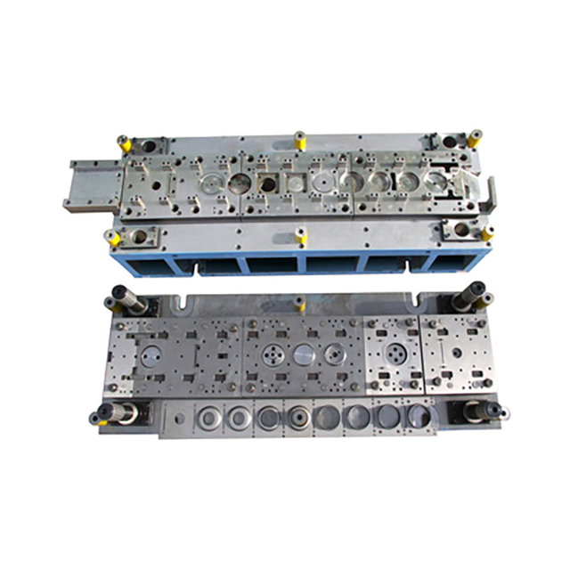
Reverse tonnage, often called snap-through shock, occurs during heavy blanking operations. As the punches push through the material, the equipment frame stretches under tension. When the material fractures, the resistance drops to zero instantly. The stretched frame snaps back to its original shape. This violent release of stored energy sends a destructive shockwave through the frame, pitman, and drive mechanism.
This shockwave severely degrades bearings, loosens fasteners, and damages internal components over time. High-speed progressive blanking amplifies this effect. To mitigate this damage, the equipment must incorporate shock dampening systems. Hydraulic shock absorbers mounted under the bed absorb the sudden release of energy, protecting the structural integrity of the frame and extending the life of the drive train.
Proper tonnage distribution across the entire die space is equally important. Concentrating high tonnage at one end of the bed exacerbates off-center loading and increases deflection. Tooling designers arrange the stations to balance the load as evenly as possible. When perfect balance is impossible, the equipment must possess the structural mass and gibbing design to handle the concentrated forces safely.
Calculating the required bed length involves more than simply measuring the physical die shoe. You must account for the entire material handling process within the die space. Overhanging dies cause severe deflection and catastrophic tooling failure.
Calculate Active Stations: Multiply the number of progressive stations by the pitch of the coil strip.
Add Material Entry Clearance: Factor in the space required for the stock guide and initial pilot holes before the first working station.
Account for Scrap Shedding: Ensure there is sufficient open space at the end of the bed for scrap cutters and part ejection chutes to operate without jamming.
Verify Clamping Margins: Leave a minimum of 10% extra bed length on both sides to accommodate heavy-duty hydraulic or mechanical die clamps.
Shut height and stroke length are critical parameters for accommodating complex, multi-stage tooling. The shut height must allow enough room for the die in its closed position, plus any necessary bolster plates. The stroke length must provide sufficient clearance for the material to feed forward without catching on the punches or pilots. Deep drawn parts require longer stroke lengths to allow the part to clear the die matrix before the strip advances.
Straight-side presses represent the industry standard for progressive die stamping. The closed-box design consists of a crown, a bed, and two vertical uprights, all held together by heavy pre-stressed tie rods. This four-point support system provides exceptional structural rigidity. The enclosed frame contains the forces generated during stamping, preventing the structure from opening up under load.
This architecture delivers zero angular deflection, commonly known as gaping. Because the frame does not yawn open, the slide remains perfectly parallel to the bed throughout the stroke. This parallelism is critical for progressive dies, where multiple punches must enter the die matrix simultaneously with micron-level precision. When sourcing a press for progressive die stamping, straight-side frames handle severe off-center loads significantly better than any other design.
The robust construction of straight-side frames also dampens vibration effectively. Reduced vibration extends punch life, improves part finish, and protects sensitive electronic sensors mounted on the tooling. For high-volume, high-precision progressive stamping, the straight-side architecture is the only viable choice for long-term stability.
C-frame presses feature an open-front design that resembles the letter "C". This design provides excellent access to the die space from three sides, making setup and material feeding easier. However, this open architecture introduces severe inherent limitations. Under heavy loads, the open front of the frame flexes outward. This flexing is known as yaw or angular deflection.
When a C-frame yawns, the slide tilts away from the bed. This tilt destroys the parallelism required for progressive stamping. Punches enter the die matrix at an angle, causing rapid wear, chipped cutting edges, and out-of-tolerance parts. The severity of the deflection increases exponentially as the tonnage approaches the machine's maximum capacity.
C-frames have very narrow use cases in progressive stamping. They are acceptable only for very light, short progressive dies with low tonnage requirements and minimal off-center loading. For operations involving heavy blanking, coining, or long multi-station dies, the angular deflection of a C-frame inevitably leads to unacceptable part quality and excessive tooling maintenance.
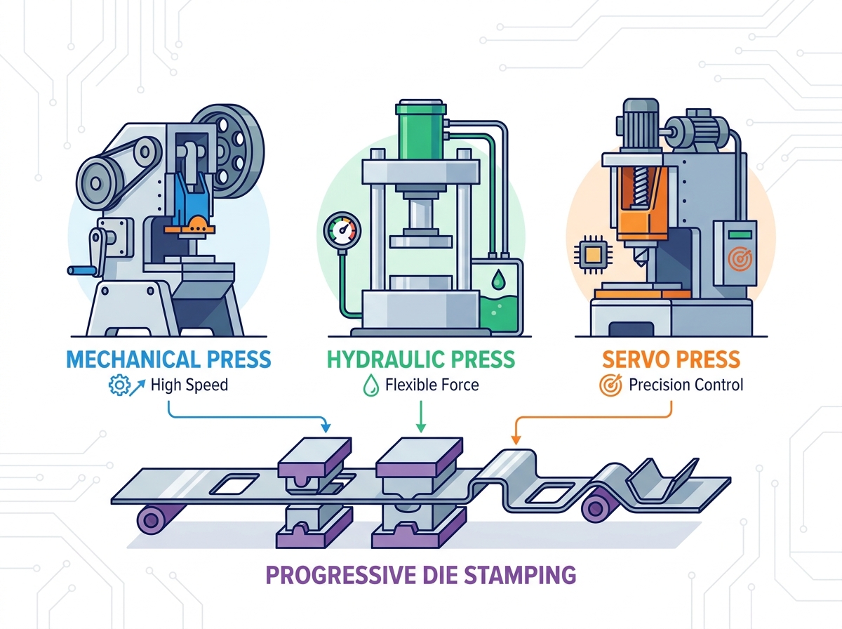
Mechanical stamping presses rely on a heavy rotating flywheel and a clutch/brake system to store and deliver energy. An electric motor spins the flywheel continuously. When the operator triggers the cycle, the clutch engages, connecting the flywheel to the crankshaft. The crankshaft converts the rotary motion into the linear motion of the slide. This design is highly efficient for delivering massive force quickly.
The primary advantage of mechanical drives is their ability to deliver high kinetic energy exactly at bottom dead center. This characteristic makes them ideal for high-volume, continuous blanking and piercing operations. Mechanical drives achieve the highest strokes per minute (SPM) in the industry. They are proven, reliable workhorses capable of running continuously for decades with proper maintenance.
However, mechanical drives have a fixed stroke profile. The speed of the slide follows a mathematical sine wave, reaching maximum velocity mid-stroke and slowing down as it approaches BDC. You cannot alter this motion profile. This lack of flexibility makes mechanical drives less suitable for complex forming operations that require slow drawing speeds or dwell time at the bottom of the stroke.
Servo-driven stamping presses replace the traditional flywheel, clutch, and brake with high-torque, direct-drive servo motors. These motors connect directly to the drive shaft, providing absolute control over the slide's position, velocity, and acceleration at every millimeter of the stroke. This technology represents a massive leap forward in stamping flexibility.
The greatest advantage of servo drives is the programmable stroke profile. Operators program variable speeds within a single cycle. The slide approaches the material quickly, slows down precisely during the forming phase to prevent tearing, and then retracts rapidly to maximize production speed. Servo drives also offer dwell capabilities, allowing the slide to pause at BDC for complex in-die operations like tapping, hardware insertion, or intricate coining.
Servo technology enables pendulum mode. The slide does not need to complete a full 360-degree rotation. It oscillates up and down just enough to clear the material, significantly increasing cycle rates for shallow parts. The trade-off for this advanced capability is a higher initial capital expenditure and the need for specialized maintenance personnel trained in advanced motion control systems.
Hydraulic stamping presses use fluid pressure acting on a piston to generate force. A hydraulic pump drives oil into a cylinder, pushing the ram downward. The defining characteristic of a hydraulic drive is its ability to deliver full, constant tonnage throughout the entire stroke. Unlike mechanical drives, which only reach peak tonnage near BDC, hydraulic drives apply maximum force at any point.
This constant force delivery makes hydraulic drives ideal for deep-draw progressive work. Deep drawing requires sustained pressure over a long distance to pull the metal into the die cavity without tearing. Hydraulic systems also dwell at the bottom of the stroke under full pressure, which is beneficial for setting complex forms or curing specific materials.
Despite these advantages, hydraulic drives have significant limitations for general progressive stamping. They suffer from slower cycle times compared to mechanical or servo alternatives. Furthermore, hydraulic systems are highly vulnerable to snap-through shock. The sudden release of pressure during heavy blanking damages hydraulic seals, valves, and fittings, causing leaks and system failures. Therefore, they are rarely used for high-speed blanking.
Drive Type | Force Curve Characteristic | Speed (SPM) | Best Progressive Application |
|---|---|---|---|
Mechanical (Flywheel) | Peak tonnage only at BDC | Very High (100 - 1000+ SPM) | High-volume blanking, piercing, shallow forming |
Servo (Direct Drive) | Programmable, full tonnage near BDC | Medium to High (Variable) | Complex forming, in-die tapping, high-strength steel |
Hydraulic | Full tonnage throughout entire stroke | Low to Medium | Deep drawing, sustained pressure coining |
Choosing the right drive mechanism requires a clear framework balancing raw speed against process complexity. Simple blanking and piercing operations prioritize speed. The goal is to produce as many parts per minute as possible. For these applications, mechanical drives remain the superior choice. Their flywheel energy and simple rotary motion achieve cycle rates that servo and hydraulic systems struggle to match.
Conversely, process complexity demands control over speed. When a progressive die includes deep drawing, complex bending, or in-die tapping, raw speed becomes a liability. High impact velocities cause material tearing, galling, and premature tool wear. Servo drives excel here. The ability to slow the ram during the working portion of the stroke improves part quality and extends tool life, offsetting the slightly lower overall SPM.
In-die operations dictate the required cycle control. If the tooling requires a pilot release to allow the material to align perfectly before clamping, the equipment must accommodate that timing window. Servo systems allow programmers to stretch the feed window without sacrificing overall cycle time, providing a perfect balance between precision forming and production efficiency.
The operational efficiency of a progressive stamping line relies entirely on automation. The equipment must sync perfectly with servo roll feeders, straighteners, and uncoilers. Continuous strip tension is critical. If the feeder pushes material faster than the equipment cycles, the strip buckles. If it feeds too slowly, the pilots stretch the holes, ruining the progression.
Programmable logic controllers (PLCs) form the brain of the automation cell. The press control architecture must communicate seamlessly with the ancillary equipment. Modern control systems use encoder feedback to track the exact position of the crankshaft. This data triggers the feeder to advance the material only when the punches are clear of the strip.
Part ejection and scrap removal also depend on tight integration. Air blow-offs, scrap conveyors, and part sorting chutes must activate at precise moments during the stroke. A robust control architecture allows engineers to program these auxiliary functions based on crank angle, ensuring reliable, jam-free operation during high-speed production runs.

Evaluating the long-term operational footprint requires looking at power draw and maintenance schedules. Mechanical presses utilize a continuously spinning flywheel. The main motor draws heavy current constantly to keep that massive steel wheel at speed, regardless of whether the ram is cycling. Maintenance on these systems revolves around mechanical wear parts: replacing clutch friction plates, adjusting brake bands, and ensuring the rotary union receives constant lubrication.
Servo presses operate on an entirely different power profile. The direct-drive motors only draw significant power when moving the ram under load. During idle times or the non-working portion of the stroke, power consumption drops drastically. Many modern servo systems also utilize regenerative braking, capturing kinetic energy during the ram's deceleration and feeding it back into a capacitor bank. Maintenance for servo systems shifts away from mechanical wear parts toward electronic health. Technicians monitor encoder signals, check cooling fan operation on the drives, and verify the integrity of heavy-duty power cables.
High-speed progressive operations carry a significant risk of catastrophic die crashes. Misfeeds, where the material does not advance the correct distance, cause punches to hit solid metal instead of the intended cavities. Slug pulling, where scrap metal sticks to the punch and retracts back into the die space, causes double-thick material conditions on the next stroke. Both scenarios destroy expensive tooling instantly.
Implementing comprehensive sensor networks is mandatory for progressive stamping.
Short-Feed Sensors: Verify the material has advanced to the exact correct position before the ram descends. If the sensor does not detect the material edge, it triggers an emergency stop.
Part Ejection Sensors: Optical sensors and proximity switches monitor the exit chute, ensuring the die space is clear before the next cycle begins.
Tonnage Monitors: Measure the force exerted during every stroke. If a slug pulls or a punch dulls, the required tonnage spikes. The monitor detects this anomaly and halts the equipment immediately.
Acoustic Monitoring: Detects the specific sound frequencies of a failing punch or a misfeed, stopping the cycle before catastrophic damage occurs.
Installing high-tonnage straight-side equipment requires extensive structural facility planning. The static weight of the machinery is immense, but the dynamic forces generated during operation are far more severe. Standard factory floors cannot support these loads. The concrete will crack, and the equipment will settle unevenly, destroying its internal alignment.
Facilities construct specialized foundations for this equipment. This involves excavating the floor and pouring a massive, steel-reinforced concrete inertia block. The mass of this block absorbs the kinetic energy generated by the stamping process. The foundation must be engineered specifically for the dynamic loads of the specific equipment model being installed.
Vibration isolation protects surrounding equipment and building integrity. Severe stamping vibrations interfere with precision machining centers, coordinate measuring machines (CMMs), and sensitive electronics nearby. Engineers use heavy-duty isolation mounts or spring dampers between the equipment feet and the foundation block to decouple the vibration from the surrounding facility floor.
Transitioning a facility from traditional mechanical equipment to advanced servo or specialized hydraulic systems creates a significant skills gap. Operators accustomed to simply pushing a start button must now understand complex motion profiles. Maintenance personnel familiar with greasing bearings and adjusting clutch plates must learn to troubleshoot electronic drives, encoders, and hydraulic valving.
Comprehensive training programs are essential. Operators learn how to program stroke profiles to optimize forming without damaging the tooling. They understand how to set up complex coil feed lines, adjust pilot release timing, and interpret data from tonnage monitors. Incorrect programming on a servo drive causes severe tooling damage just as easily as a mechanical failure.
Maintenance protocols evolve with the technology. Electronic drive components require clean environments and stable power supplies. Preventative maintenance shifts from purely mechanical inspections to software updates, sensor calibration, and thermal monitoring of servo motors. Facilities invest in upskilling their workforce to realize the full potential of advanced stamping technology.
Conduct a comprehensive tonnage and off-center load analysis with your tooling engineers to determine the true force requirements of your most demanding progressive dies.
Evaluate your facility's foundation capacity and plan for necessary structural upgrades or vibration isolation systems before finalizing any equipment purchase.
Map out the required automation integration, ensuring the new equipment controls communicate seamlessly with your existing coil feeding and scrap removal systems.
Develop an upskilling program for your maintenance and operation teams to ensure they effectively program and troubleshoot advanced servo or sensor-heavy systems.
For manufacturers building or upgrading progressive stamping lines, Zhejiang Jinaolan Machine Tool brings decades of experience in precision stamping equipment and integrated production-line solutions. Founded in 1983, the company manufactures mechanical presses from 25 to 2,400 tons and has expanded its capabilities to progressive die stamping lines, feeding systems, stamping dies, transfer equipment, and intelligent press controls.
A: Straight-side presses feature a closed-box design with four-point support, eliminating the angular deflection common in open-front C-frames. This rigidity maintains strict parallelism between the ram and bed under heavy, off-center loads, preventing premature punch wear and ensuring precise part tolerances across multi-station dies.
A: Progressive dies process a continuous coil strip through multiple sequential stations simultaneously. This creates uneven, off-center loading across the bed. The equipment must possess high structural rigidity to resist tipping moments and integrate seamlessly with automated coil feeders to maintain precise strip tension and progression pitch.
A: Mechanical presses use a continuously spinning flywheel and clutch to deliver high kinetic energy and maximum speed, ideal for high-volume blanking. Servo presses use direct-drive motors to provide programmable stroke profiles, variable speeds, and dwell times, making them superior for complex in-die forming and drawing operations.
A: Blanking requires high kinetic energy exactly at bottom dead center to fracture the metal quickly. Coining requires immense squeezing pressure at the end of the stroke. Deep drawing needs sustained, controlled force. The equipment's drive mechanism must match the specific force curve demanded by these operations to prevent stalling.
A: While hydraulic presses provide constant tonnage excellent for deep drawing, they are generally unsuitable for high-speed progressive blanking. They have slower cycle times and are highly vulnerable to snap-through shock, which damages hydraulic seals and valves when the material suddenly fractures during heavy blanking operations.
A: Snap-through shock occurs when punches break through the material during heavy blanking. The sudden release of resistance causes the stretched frame to violently snap back. This shockwave damages bearings, loosens fasteners, and degrades the drive train over time, requiring robust shock dampening systems to protect the machinery.



