Guide Plate Single Stage Blanking Die

1- Die shank
2- Stop pin
3- Upper die seat
4- Inner hex screw
5- Punch die
6- Backing plate
7- Punch die fixing plate
8- Inner hex screw
9- Guiding plate
10- Material guiding plate
11- Material bearing plate
12- Screw
13- Cavity die
14- Round pin
15- Lower die seat/ die holder
16- Fixed stop pin
17- stop pin
18- Limit pin
19- Spring
20- Trigger stop pin
Structure and principle of guide plate single stage blanking die
Figure is a simple guide plate blanking die. The guidance of the upper and lower dies is based on the clearance between guide plate 9 and punch 5, so called guide plate die.
Die’s working parts are punch 5 and cavity 13; positioning pars are guide plate 10 and fixed stop pin 16, trigger stop pin 20; guiding part is guide plate 9 (acts also as a fixed stripper plate); supporting parts are punch fixing plate 7, backing plate 6, upper die seat 3, die shank 1, die holder 15; In addition, there are fastening screws, pins etc. According to die layout, the position of the fixed stop pin of this die will not be able to position the first punching. For this purpose, the trigger stop pin 20 is used. Before first punching, trigger stop pin will be pressed by manual to limit the strip material. In the subsequent punching, the stop pin will begin to be used and trigger stop pin is ejected by the spring.
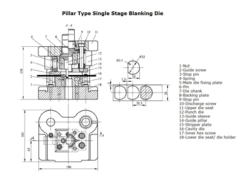
Pillar Type Single Stage Blanking Die

1- Nut
2- Guide screw
3- Stop pin
4- Spring
5- Male die fixing plate
6- Pin
7- Die shank
8- Backing plate
9- Stop pin
10- Discharge screw
11- Upper die seat
12- Punch die
13- Guide sleeve
14- Guide pillar
15- Stripper plate
16- Cavity die
17- Inner hex screw
18- Lower die seat/ die holder
Structure and principle of guide pillar single-stage blanking die
Figure shows the pillar type blanking die. The correct position of the upper and lower die is ensured by the guide column 14 and guide sleeve 13. Before punching of the male and female dies, the guide pillar has entered the guide sleeve, thereby ensuring the uniformity of the clearance between the punch die 12 and the cavity die 16 during the blanking process.
Upper and lower die seats, and guide pillar and guide sleeve are assembled to die frame. The cavity 16 is fastened with lower die holder 18 by hexagon screw for positioning. The punch 12 is fastened with upper die holder for positioning by fixing plate 5, screws, pins. The rear side of punch die is fixed with back plate 8.
Press-in type die shank 7 is fitted into the upper die holder and prevented from rotating by stop pin 9.
Strip material is sent along the guiding bolt 2 to the stripper pin 3 for the positioning and blanking. The material hooped on the punch is discharged by elastic pressure device which is composed of a stripper plate 15, discharging screw 10 and spring 4. Before blanking operation is performed on the male and female dies, discharging plate will press material at first under the force of the spring, and then the upper mold continues pressing down to perform punching separation, at the time the spring is compressed. When upper mold returns, the spring recovers and pushes the discharging plate to unload the material hooped on the punch.
Functions of guide pillar and guide sleeve: They play as a guide in the die and ensure that the punch die and cavity die have the correct relative position during operation and the movable part of die frame moves smoothly without blocking.
Blade Gap Adjustment
1.Fix the upper die with hexagon screws, and do not tighten the hexagon screws in the lower die.
2.Close the upper and lower die seats. Carefully observe when the punch die is close to the cavity die and slowly insert the punches into die holes. If there is an error, use a copper rod to tap the cavity, and try again to see if it can be accessed. If it does not work, adjust it until the punch enters 0.5mm in the mouth of the cavity.
3.After the adjustment, tighten the hexagon screw head of the lower die.
4.Slightly separate the upper and lower die seats, test them with paper, and observe if there are any rough edges on the section. If the section has rough edges, adjust the blade edge until it is satisfactory.
Non-guided Single Stage Blanking Die

1- Upper die seat
2- Punch die
3- Discharging plate
4- Guiding plate
5- Cavity die
6- Lower plate
7- Positioning plate


