Home
Products
Power Press
Stamping Die
Stamping Automation
Auto Feeder
About Us
Brands
Infrastructure
Qualification
Download
Video
Projects
Service
Blogs
Contacts
:
All
Product Name
Product Keyword
Product Model
Product Summary
Product Description
Multi Field Search
العربية
Pусский
Español
Português
Deutsch
Tiếng Việt
ไทย
Türk dili
हिन्दी
فارسی
Inquiry Us
:
All
Product Name
Product Keyword
Product Model
Product Summary
Product Description
Multi Field Search
Home
Products
Power Press
Stamping Die
Stamping Automation
Auto Feeder
About Us
Brands
Infrastructure
Qualification
Download
Video
Projects
Service
Blogs
Contacts
PRODUCT
Home
/
Products
Explore High-Precision Tandem Press Lines & Feeding Systems
Add to Cart
Inquire
Add to Cart
Inquire
Metal Pall Ring Production Line CNC Power Press Automatic Feeder Mold
Add to Cart
Inquire
Add to Cart
Inquire
CNC Single Column Press Punching Machine Shoes Automatic Eyelet making Machine
Add to Cart
Inquire
Add to Cart
Inquire
Brass Tee Brass Valve Automatic Power Press Making Machine Stamping Machine
Add to Cart
Inquire
Add to Cart
Inquire
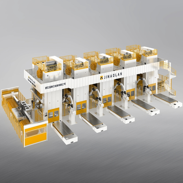
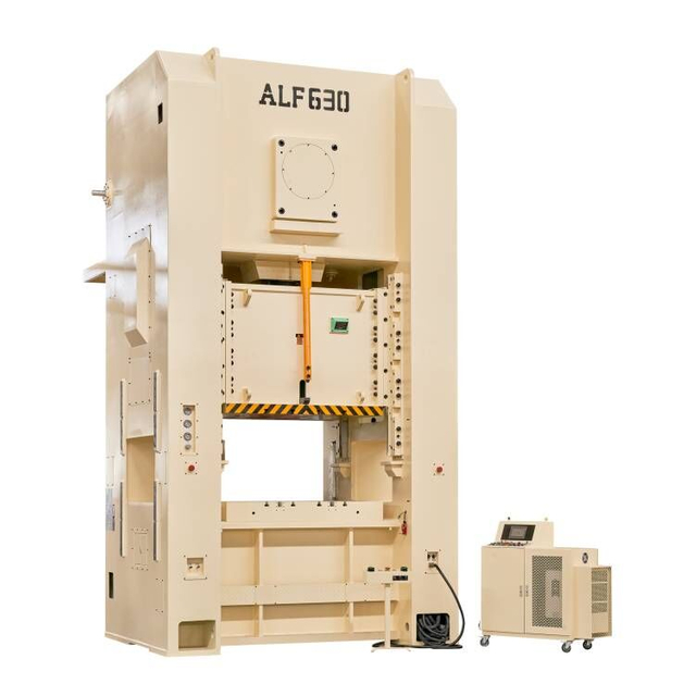
T4 MULTIPLE PRESSES AUTOMATION LINE
Add to Cart
Inquire
Add to Cart
Inquire
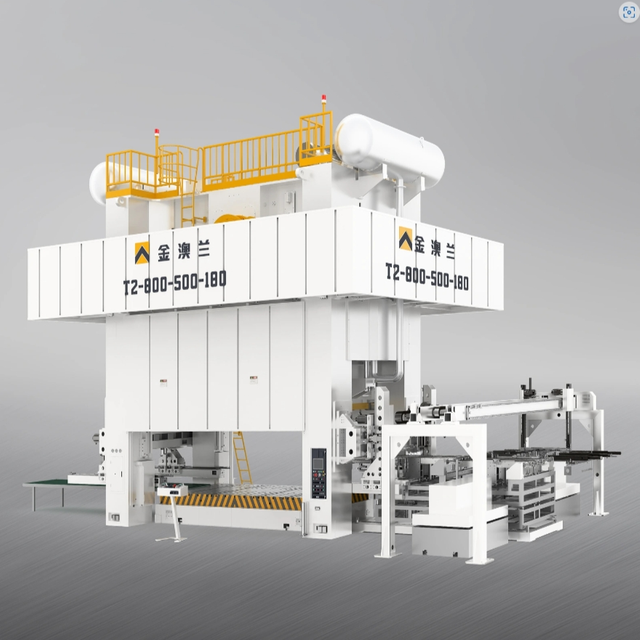
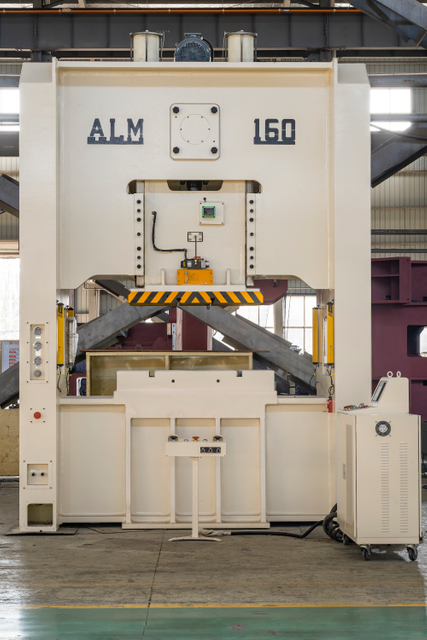
T2 MULTIPLE PRESSES AUTOMATION LINE
Add to Cart
Inquire
Add to Cart
Inquire
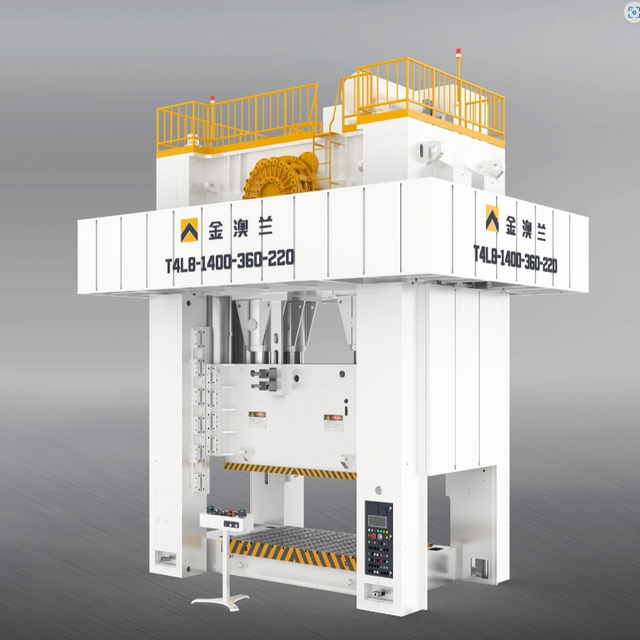
T4L8 FOUR POINT STRAIGHT SIDE EIGHT LINK MOTION TYPE POWER PRESS
Add to Cart
Inquire
Add to Cart
Inquire
Brass Copper Crush Sealing Washer Flat Seal Gasket Ring Automatic Punching Making CNC power Press Machine
Add to Cart
Inquire
Add to Cart
Inquire
Motor stator rotor making machine Stator rotor punching machine
Add to Cart
Inquire
Add to Cart
Inquire
automatic hot forging press machine for valve pneumatic stamping machine for brass refrigerant tee production
Add to Cart
Inquire
Add to Cart
Inquire
Power Press Machine of Making Shovel And Hammer And Broom Wooden Handle
Add to Cart
Inquire
Add to Cart
Inquire
Lighter metal body full automatic power press making machine line
Add to Cart
Inquire
Add to Cart
Inquire
Spring hinge High performance full automatic press of stainless steel hinge production line
1
2
3
4
...
8
»
:
All
Product Name
Product Keyword
Product Model
Product Summary
Product Description
Multi Field Search
Product Category
Power Press
C Frame Power Press
H Frame Power Press
Eccentric Gear and Multi-link Press
Stamping Die
Single Stage Die
Transfer Die
Progressive Die
Stamping Automation
2D Manipulator
3D Manipulator
Robot Arm
Auto Feeder
NC Servo Feeder
Decoiler Straightener 2 in 1 Machine
3 in 1 Decoiler Straightener and Feeder
sales@kinglanpress.com
Tel: +86-21-5410-0878
Fax: +86-21-5410-8802
Add: No 19, Huanglong 3rd Road, Huanglong Industrial Zone, Wuyi, Zhejiang, China
+86-21-5410-0878
sales@kinglanpress.com
Leave a Message
Online Message
Product Category
Power Press
Stamping Die
Stamping Automation
Auto Feeder
Submit
Quick Links
Home
About
Projects
Service
Blogs
Contact
Products
Power Press
Stamping Die
Stamping Automation
Auto Feeder
About
Brands
Infrastructure
Qualification
Download
Video
Copyright ©
2024
Zhejiang Jinaolan Machine Tool Co., Ltd. All Rights Reserved.
Privacy Policy
|
SiteMap
| Support By
Leadong